Renewable Energy Process and Method of Using a Carbon Dioxide Cycle
| ✓ Paper Type: Free Assignment | ✓ Study Level: University / Undergraduate |
| ✓ Wordcount: 5171 words | ✓ Published: 26 Oct 2021 |
Abstract
In this report the results of a study of a renewable energy system from a given patent are presented. The energy system uses a low heat source to run a carbon dioxide cycle. The system and its possible field of operation are described. Energy and exergy balance equations and exergy efficiency for all systems components are provided.
All state points for the carbon dioxide cycle are calculated and listed. Energy and exergy efficiency of the overall system and its component are provided. The cycle is displayed in an T-s- and p-h- diagram. To evaluate different operation strategies, parametric studies were made. Slightly higher energy efficiencies and higher exergy efficiencies were achieved with a higher mass flow of carbon dioxide, a higher cycle temperature and a smaller amount of mass flow in path A refereed to path B.
An alternate carbon dioxide cycle with an even higher energy efficiency is introduced and presented. A special focus on environmental impact and sustainability for both cycles is given at the end of the report.
CONTENTS
1 Introduction 2
2 System Description 2
2.1 Powerplant Cycle . . . . . . . . . . . . . . 2
2.2 Carbon Dioxide Cycle (System 1) . . . . . 2
3 Energy Analyses 3
4 Exergy Analyses 4
5 Energy and Exergy Efficiency 5
5.1 Energy efficiency . . . . . . . . . . . . . . 5
5.2 Exergy efficiency . . . . . . . . . . . . . . 5
6 Analyses System 1 6
6.1 Assumptions . . . . . . . . . . . . . . . . 6
6.2 Results of Analyses . . . . . . . . . . . . . 6
7 Parametric Study of System 1 9
7.1 Reference Temperature . . . . . . . . . . . 9
7.2 Temperature Carbon Dioxide Cycle . . . . 9
7.3 Mass Flow Water . . . . . . . . . . . . . . 10
7.4 Mass Flow Carbon Dioxide . . . . . . . . . 10
7.5 Mass Split Path A-B . . . . . . . . . . . . 10
8 Alternate Carbon Dioxide Cycle 10
8.1 System Description Alternate Carbon Dioxide Cycle (System2) . . . . . . . . . . . . . 10
8.2 Assumptions . . . . . . . . . . . . . . . . 11
8.3 Results of Analyses . . . . . . . . . . . . . 11
9 Environmental Impact and Sustainability 13
10 Conclusions 14
Nomenclature
CO2 Carbon dioxide
N2 Nitrogen
Evap Evaporator
Comp Compressor
HX Heat exchanger
DTV Deposition- transition- vessel
VN Venturi nozzle
1 Introduction
The use of renewable energy systems has a key role to ensure a sustainable energy supply. With the renewable system by Calvin Eugene Phelps (Patent Pub. No.: US2019/0170025 A1) a new approach is presented [1]. The task of the course project of the lecture Advanced Energy Systems is to:
- study the system conceptually correct.
- analyze the system energetically and exergetically.
- to asses energy and exergy efficiencies for the system and all its components.
- to determine exergy destructions for all systems.
- to undertake parametric studies.
- to evaluate the system from the environmental impact and sustainability viewpoints.
All topics are presented in the following report.
First, the given systems and examples for its usage will be explained in section 2. The defined state points of the working fluid will be shown. Then, all balance equations for all components of the system will be listed in section 3 and 4. A special focus on the energy and exergy efficiencies is given in section 5. The results of the system study are presented in section 6 and 8.3. In this section all state properties are listed in tables, the process is shown in a p-h-diagram and in a T-s-diagram. Also, the exergy destructions of the system are discussed. The parametric studies for different operation strategies and reference states are presented and discussed in section 7. Last, all results and observations are listed in section 10.
All figures, tables, state properties and operation strategies are based on the Patent (Patent Pub. No.: US2019/0170025 A1) by Calvin Eugene Phelps.
2 System Description
The renewable energy systems presented by Calvin Eugene Phelps can be applied in various different operations, like solar heated ponds, geothermal sources or powerplant condensers [1]. Their main advantage is to use a low heat source to run a carbon dioxide cycle. For this system study the systems will be used to convert heat loss from a Powerplant condenser to electrical energy.
2.1 Powerplant Cycle
Any Powerplant condenser can be used for this application. The carbon dioxide cycles are applied additional to the power plant without a need of change in the operation strategies to increase its over-all efficiency [1]. In this application, the waste heat from the condenser will be used as a low heat energy source.
2.2 Carbon Dioxide Cycle (System 1)
The carbon dioxide cycle is show in figure 1. All changes of the properties of the working fluid CO2 are described with the state points shown in 1. In the rest of the report it will be referred as system 1.
Carbon Dioxide is heated up to saturated vapor in the evaporator (30) by a low heat source (waste heat form power plant condenser). Then, the flow then is split up in three different parts: path A, path B and path C.
Path B is guided through a throttling valve into compressor (31) to superheated supercritical vapor. The compressor is connected to turbine (32-2) and receives the compression work for the expansion of Path A. After the compression (state 15) path B is split up into two parts. The paths enter two different heat exchangers (30-1 and 30-2) and get recombined (state 20). The superheated liquid expands through a turbo expander (32-3) generating electrical energy (G3) and gets recombined with path A and path C (41).
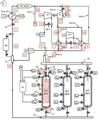
Fig. 1. Carbon dioxide cycle (system 1) with state points of working fluid [1]
Path A is heated up to superheated vapor by the first part pf path B in the first heat exchangers (30-1) and expands isentropic in a turbine (32-1) to generate electric energy by a generator (G1). Path A is heated up again by a heat exchanger (30-2) and expands again isentropic in a second turbine (32-2). The expansion energy is used to supply the compressor with work for its compression and to generate again electrical energy (G2). The low pressure superheated vapor expands again in a turbo expander (32-4) generating additional electric work (G4) and is directed to a depositiontransition vessels (DT 33).
Path A (state 9) is directed through a throttling valve (35) and a venturi nozzle (36) in the DT- vessel (state 10.1). Nitrogen is sprayed to the DT- vessel at a low temperature and a pressure to receive a partial atmospheric pressure of the CO2– vapor to guarantee dry ice deposition (state 10.2). After the vessels receives its full amount of dry ice, all nitrogen is removed from the vessel (state 10.4) and it is pressurized by path C to a pressure above the triple point to prevent sublimation (state 10.4). The rest of path C is heating and pressurizing the dry ice. Through this process the dry ice transitions to a sub-cooled liquid (state 10.5). By inserting nitrogen again in the DT- vessel the liquid gets pressurized (state 10.6) and replaced by flowing to a mixing chamber (12). The recombined paths A and C recombine at 41 with path B and restart the process.

3 Energy Analyses
The energy balance equations for the carbon dioxide cycle and its components are shown in the following sections. All state points, generated energies and efficiencies were calculated with these equations.
Evaporator 30
The energy balance equation for Evaporator (30) is shown in equation 1.
m˙ ABC h2 +Q˙evap,in = m˙ ABC h3 (1)
The energy transferred from the low heat source to the working fluid is calculated by equation 2.
Q˙evap,in = m˙ W (hw1 −hw2) (2)
Compressor 31
The energy balance equation for Compressor (31) is shown in equation 3.
m˙ B h14 +W˙comp = m˙ B h15 (3)
The work from for the compression process W˙comp is generated by Turbine 32.2 (see equation 7).
Heat Exchanger 30-1
The energy balance equation for heat exchanger (30-1) is shown in equation 4.
m˙ A h4 +m˙ B1 h16 = m˙ A h5 +m˙ B1 h17 (4)
Turbine 32-1
The energy balance equation for turbine (32-1) is shown in equation 5.
m˙ A h5 = m˙ A h6 +W˙out,Turbine321 (5)
Heat Exchanger 30-2
The energy balance equation for heat exchanger (30-2) is shown in equation 6.
m˙ A h6 +m˙ B2 h18 = m˙ A h7 +m˙ B2 h19 (6)
Turbine 32-2
The energy balance equation for turbine (32-2) is shown in equation 7.
m˙ A h7 = m˙ A h8 +W˙comp +W˙out,Turbine322 (7)
The work W˙comp is used in the compression process (see equation 3).
Turbine 32-3
The energy balance equation for liquid turbo expander (323) is shown in equation 8.
m˙ B h20 = m˙ B h21 +W˙out,Turbine323 (8)
Turbine 32-4
The energy balance equation for turbo expander (32-4) is shown in equation 9.
m˙ A h8 = m˙ A h9 +W˙out,Turbine324 (9)
DT- Vessel
Several processes happen in the DT- Vessel. These processes are simplified as an open process with continuous flow through the vessel. Mixing processes of carbon dioxide with nitrogen is neglected. The injection of nitrogen is simplified as heat sink/ source.
The energy balance equation for the venturi nozzle is shown in equation 10.
m˙ A h10 = m˙ A h101 +Q˙SN21 (10)
After that, Nitrogen is injected to the system (see equation
11)
m˙ A h101 = m˙ A h102 +Q˙SN22 (11)
After the deposition of carbon dioxide to dry ice, the Nitrogen is removed. A part of Path C is mixed to Path A. The energy balance equation is given in equation 12.
splitC m˙C h22 +m˙ A h103 =(splitC m˙C +m˙ A) h104 (12) The rest of Path C is mixing with Path A (see equation 13).
(splitC m˙C +m˙ A) h104 +(1−splitC) m˙C h22 =
(13) (m˙ A +m˙C) h105 Nitrogen is injected again. The energy balance equation for this process is shown in equation 14.
(m˙ A +m˙C) h105 +Q˙DTV5 =(m˙ A +m˙C) h106 (14)
4 Exergy Analyses
The exergy balance equations for the carbon dioxide cycle and its components are shown in the following sections. All state points, generated energies and efficiencies were calculated with these equations.
Evaporator 30
The exergy balance equation for Evaporator (30) is shown in equation 15.
m˙ ABC ex2 +Ex˙ QEvap,in = m˙ ABC ex3 +Ex˙ D,evap (15)
The exergy destruction for the heat from low heat source to the working fluid Ex˙ QEvap,in is calculated by equation 16.
Ex˙ QEvap,in  Q˙evap,in (16)
Temperature Tevap as source temperature for heat transfer is the output temperature Tw1 of power plant.
Compressor 31
The exergy balance equation for Compressor (31) is shown in equation 17.
m˙ B ex14 +W˙comp = m˙ B ex15 +Ex˙ D,comp (17)
Heat Exchanger 30-1
The exergy balance equation for heat exchanger (30-1) is shown in equation 18.
m˙ A ex4 +m˙ B1 ex16 = m˙ A ex5 +m˙ B1 ex17 +Ex˙ D,HX301 (18)
Turbine 32-1
The exergy balance equation for turbine (32-1) is shown in equation 19.
m˙ A ex5 = m˙ A ex6 +W˙out,Turbine321 +Ex˙ D,Turbine321 (19)
Heat Exchanger 30-2
The exergy balance equation for heat exchanger (30-2) is shown in equation 20.
m˙ A ex6 +m˙ B2 ex18 = m˙ A ex7 +m˙ B2 ex19 +Ex˙ D,HX302 (20)
Turbine 32-2
The exergy balance equation for turbine (32-2) is shown in equation 21.
m˙ A ex7 = m˙ A ex8 +W˙comp +W˙out,Turbine322 +Ex˙ D,Turbine322
(21)
Turbine 32-3
The exergy balance equation for liquid turbo expander (323) is shown in equation 22.
m˙ B ex20 = m˙ B ex21 +W˙out,Turbine323 +Ex˙ D,Turbine323 (22)
Turbine 32-4
The exergy balance equation for turbo expander (32-4) is shown in equation 23.
m˙ A ex8 = m˙ A ex9 +W˙out,Turbine324 ++Ex˙ D,Turbine324 (23)
DT- Vessel
Several processes happen in the DT- Vessel. These processes are simplified as an open process with continuous flow through the vessel. Mixing processes of carbon dioxide with nitrogen is neglected. The injection of nitrogen is simplified as heat sink/ source.
The exergy balance equation for the venturi nozzle is shown in equation 42.
m˙ A ex10 = m˙ A ex101 +Ex˙ SN21 (24)
with

 Ex˙ QSN21
  T0 1 Q˙QSN21 (25)
Tsource,VN36
After that, Nitrogen is injected to the system (see equation 43)
with
m˙ A ex101 = m˙ A ex102 +Ex˙ SN22
(26)
Q

 T0˙SN22 (27)
Ex˙ QSN22 = 1 Q
Tsource,DTV1
After the deposition of carbon dioxide to dry ice, the Nitrogen is removed. A part of Path C is mixed to Path A. The exergy balance equation is given in equation 44.
splitC m˙C ex22 +m˙ A ex103 =(splitC m˙C +m˙ A) ex104 (28) The rest of Path C is mixing with Path A (see equation 45).
(splitC m˙C +m˙ A) ex104 +(1−splitC) m˙C ex22 =
(29) (m˙ A +m˙C) ex105
Nitrogen is injected again. The exergy balance equation for this process is shown in equation 46.
(m˙ A +m˙C) ex105 +Ex˙ QDTV5 =(m˙ A +m˙C) ex106 (30) with
 Ex˙ QDTV5 = T0 1 Q˙DTV5 (31)
Tsource,DTV5
5 Energy and Exergy Efficiency
The energy and exergy efficiency for the system and its components are shown in this section.
5.1 Energy efficiency
The energy efficiency of the system is defined by the ratio of the overall energy output to the overall energy input (see equation 32).
Energy output
ηen,overall =
Energy input
 W˙Generator,overall +W˙comp (32)
=
Q˙evap,in +W˙comp
The overall generated electric energy is calculated by equation 33.
W˙Generator,overall =W˙Generator,321 +W˙Generator,322
(33) +W˙Generator,323 +W˙Generator,324
5.2 Exergy efficiency
Evaporator 30
The exergy efficiency of evaporator (30) is shown in equation 34.
mABC˙ (ex3 −ex2)
ψEvap =  (34) m˙W (exw1 −exw2)
Compressor 31
The exergy efficiency of compressor (31) is shown in equation 35.
ψComp  (35)
(35)
Heat Exchanger 30-1
The exergy efficiency of heat exchanger (30-1) is shown in equation 36.
m˙ A (ex5 −ex4)
ψHX301 =  (36) m˙ B1 (ex16 −ex17)
Turbine 32-1
The exergy efficiency of heat turbine (32-1) is shown in equation 37.
ψTurbine (37)
(37)
Heat Exchanger 30-2
The exergy efficiency of heat exchanger (30-2) is shown in equation 38.
m˙ A (ex7 −ex6)
ψHX302 = (38) m˙ B2 (ex18 −ex19)
Turbine 32-2
The exergy efficiency of heat turbine (32-2) is shown in equation 39.
ψTurbine (39)
(39)
Turbine 32-3
The exergy efficiency of heat liquid turbo expander (32-3) is shown in equation 40.
ψTurbine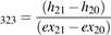 (40)
(40)
Turbine 32-4
The exergy efficiency of heat turbo expander (32-4) is shown in equation 41.
ψTurbine (41)
(41)
DT- Vessel
Several processes happen in the DT- Vessel. These processes are simplified as an open process with continuous flow through the vessel. Mixing processes of carbon dioxide with nitrogen is neglected. The injection of nitrogen is simplified as heat sink/ source.
The exergy efficiency for the venturi nozzle is shown in equation 42.
Ex˙ QSN21
ψVN36 = (42) m˙ A (ex10 −ex101)
After that, Nitrogen is injected to the system (see equation
43)
T0 S˙gen,DTV1
ψDTV1 = 1−  (43)
(43)
m˙ A (ex102 −ex101)
After the deposition of carbon dioxide to dry ice, the Nitrogen is removed. A part of Path C is mixed to Path A. The exergy efficiency is given in equation 44.
(splitC m˙C +m˙ A) ex104
ψDTV3 =  (44) splitC m˙C ex22 +m˙ A ex103
The rest of Path C is mixing with Path A (see equation 45).
(m˙ A +m˙C) ex105
ψDTV4 = 
(splitC m˙C +m˙ A) ex104 +(1−splitC m˙C)ex22
(45) Nitrogen is injected again. The exergy efficiency for this process is shown in equation 46.
T0 S˙gen,DTV5
ψDTV5 = 1−  (46)
(46)
(m˙ A +m˙C) (ex105 −ex106)
Overall System
The exergy efficiency of the system is defined by the ratio of the overall exergy output to the overall exergy input (see equation 47).
exergyoutput Ex˙ D,overall

 ψoverall = exergyinput = 1− ExQevap ˙comp (47)
˙ +W
The overall exergy destruction Ex˙ D,overall is the sum of all component’s exergy destruction.
6 Analyses System 1
In this section the results of analysis of the carbon dioxide cycle (System 1) are provided. The reasonable assumptions are listed in section 6.1. The energy and exergy efficiency, the possible energy output and all other fluid data are calculated with the equations of section 3, 4 and 5. The results are shown and discussed in section 6.2.
6.1 Assumptions
There were made several assumptions to calculate the properties and state points of the carbon dioxide cycle.
Overall System
– T0 = 294.15 C
– p0 = 101350Pa
– Heat loss to environment = 0
– Pump work neglected
– Refrigeration auxiliary power losses neglected
– Process in DT-Vessel: Simplified as open process
– Nitrogen injection assumed as heat sink / source, mixing processes neglected
Powerplant Cycle
– Mass flow rate of water of Powerplant: mW =6461kg/s
– Inlet Temperature Evaporator Water: 299.8 K
– Outlet Temperature Evaporator Water: 283.2 K
Carbon Dioxide Cycle
– Mass flow rate mABC = 2285kg/s
– Mass split of Path ABC in 3 equal parts (Path A, B, C)
– Mass split Path AB: Path A – Path B (0.5 = 0.5)
– Mass split Path B: Path B1 – Path B2 (0.6 = 0.4)
– Mass split Path C= 0.3
– Isentropic efficiency for compressor/ turbine ηis = 0.9
– Generator efficiency ηGen = 0.98
– Isentropic expansion in turbine 32-1
– Isentropic expansion in turbine 32-2
– Compressor 31 and turbine 32-2 are fixed connected
(compression work is generated by turbine)
– Isentropic expansion in turbine 32-2
– Pressures as given in patent [1]
– Temperature Carbon Dioxide Cycle T1 = 277.6K
– Temperature T4 = T6
– Temperature T7 as given in patent [1]
– Temperature T20 as given in patent [1]
– Temperature T10.2 = 160.9K
6.2 Results of Analyses
By using the equations form section 3, 4 and 5 and the assumptions listed in section 6.1 the system can be studied and analyzed.
State Points of System 1
The thermodynamic properties of each state points of the carbon dioxide cycle are listed in table 6.2.
T-s- Diagram
The carbon dioxide cycle (system 1) with the the calculated thermodynamic state properties is shown in a T-s- diagram for carbon dioxide (Figure 2).
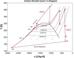
Fig. 2. T-s- diagram for carbon dioxide cycle
As described in section 2, all process steps can be seen in figure 2. Path B is compressed form state 3 to 15, then split up to heat Path A (state 15 – 17/19). This is illustrated by the long-dashed line in figure 2. The two isentropic expansions in turbine 32-1 (state 5 to 6) and in turbine 32-2 (state 7 to 8) can be seen through the vertical solid lines in figure 2. The deposition process is shown by the small-dashed line from state 101 to 102.
p-h- Diagram
For a better understanding the carbon dioxide cycle (system 1) is also shown in a h-p- diagram (Figure 3).
Especially isobaric processes can be detected easily in figure 3. Path B is shown with a long-dotted line. The decomposition process of carbon dioxide is shown be a smalldashed line (see figure 3).
Exergy Efficiencies of System Components
The exergy efficiencies of the system components are listed in table 2. They were calculated with the formulas from section 5.2.
Fig. 3. p-h- diagram for carbon dioxide cycle
Table 2. Exergy efficiencies for system 1
|
System Component |
Exergy Efficiency [%] |
|
Evaporator 30 (ψevap) |
14.11 |
|
Compressor 31 (ψCompressor31) |
92.60 |
|
Heat exchanger 30-1 (ψHX301) |
11.13 |
|
Heat exchanger 30-2 (ψHX302) |
56.31 |
|
Turbine 32-1 (ψTurbine321) |
100 |
|
Turbine 32-2 (ψTurbine322) |
100 |
|
Turbine 32-3 (ψTurbine323) |
89.77 |
|
Turbine 32-4 (ψTurbine324) |
87.21 |
|
Rejoin B (ψRejoinB) |
99.97 |
|
Rejoin ABC (ψRejoinABC) |
99.97 |
|
Venturi nozzle 36 (ψVN36) |
82.78 |
|
DT- Vessel 1 (ψDTV1) |
61.58 |
|
DT- Vessel 2 (ψDTV2) |
100 |
|
DT- Vessel 3 (ψDTV3) |
85.32 |
|
DT- Vessel 4 (ψDTV4) |
95.43 |
|
DT- Vessel 5 (ψDTV5) |
92.64 |
As shown in table 2 several processes have an exergy efficiency of 100 %, such as Turbine 32-1 and Turbine 32-2, the mixing processes Rejoin B and Rejoin ABC and the process DT- Vessel 3. All those processes are assumed to be isentropic.
The processes in Compressor 31, Turbine 32-3 and Turbine 32-4 are similar to the set isentropic efficiencies of compressor and turbine (see section 6.1).
Table 1. Thermodynamic Properties at Each State Point for the Carbon Dioxide Cycle System 1
|
State Point |
Path |
Mass Flow |
Pressure |
Temperature |
Specific Enthalpy |
Specific Entropy |
Specific Exergy |
|
– |
– |
kg s−1 |
Pa |
K |
J kg−1 |
J kg−1 K−1 |
J kg−1 |
|
1 |
ABC |
2285 |
8.27E+06 |
277.6 |
-300303 |
-1734 |
210084 |
|
2 |
ABC |
2285 |
6.21E+06 |
276.9 |
-300303 |
-1726 |
207733 |
|
3 |
ABC |
2285 |
6.21E+06 |
297.3 |
-103007 |
-1054 |
207470 |
|
4 |
A |
761.7 |
6.21E+06 |
297.3 |
-103007 |
-1054 |
207470 |
|
5 |
A |
761.7 |
6.21E+06 |
373.4 |
26614 |
-606.4 |
205278 |
|
6 |
A |
761.7 |
1.93E+06 |
297.3 |
-20373 |
-606.4 |
158291 |
|
7 |
A |
761.7 |
1.93E+06 |
383.2 |
64471 |
-355.5 |
169350 |
|
8 |
A |
761.7 |
517107 |
286.1 |
-15432 |
-355.5 |
89447 |
|
9 |
A |
761.7 |
172369 |
226 |
-61210 |
-332.7 |
36952 |
|
10 |
A |
761.7 |
172369 |
226 |
-61210 |
-332.7 |
36952 |
|
10.1 |
A |
761.7 |
101353 |
197.5 |
-81985 |
-332.7 |
16177 |
|
10.2 |
A |
761.7 |
101353 |
160.9 |
-534974 |
-2794 |
287102 |
|
10.3 |
A |
761.7 |
101353 |
160.9 |
-534974 |
-2794 |
287102 |
|
10.4 |
A, Part of C |
990.21 |
689476 |
212.2 |
-435289 |
-2258 |
229266 |
|
10.5 |
AC |
1523.4 |
8.27E+06 |
269.3 |
-318990 |
-1802 |
211498 |
|
10.6 |
AC |
1523.4 |
8.27E+06 |
272.5 |
-311968 |
-1777 |
210895 |
|
11 |
AC |
1523.4 |
8.27E+06 |
272.5 |
-311968 |
-1777 |
210895 |
|
12 |
AC |
1523.4 |
8.27E+06 |
272.5 |
-311968 |
-1777 |
210895 |
|
13 |
B |
762.7 |
6.21E+06 |
297.3 |
-103007 |
-1054 |
207470 |
|
14 |
B |
762.7 |
6.21E+06 |
297.3 |
-103007 |
-1054 |
207470 |
|
15 |
B |
762.7 |
2.45E+07 |
398.9 |
-46550 |
-1040 |
259748 |
|
16 |
B1 |
457 |
2.45E+07 |
398.9 |
-46550 |
-1040 |
259748 |
|
17 |
B1 |
457 |
2.45E+07 |
299 |
-262585 |
-1663 |
226936 |
|
18 |
B2 |
304.7 |
2.45E+07 |
398.9 |
-46550 |
-1040 |
259748 |
|
19 |
B2 |
304.7 |
2.45E+07 |
301 |
-258661 |
-1650 |
227013 |
|
20 |
B |
762.7 |
2.44E+07 |
299.8 |
-261015 |
-1658 |
226891 |
|
21 |
B |
762.7 |
8.27E+06 |
287.1 |
-276972 |
-1651 |
209116 |
|
22 |
C |
762.7 |
6.21E+06 |
297.3 |
-103007 |
-1054 |
207470 |
|
23 |
ABC |
2285 |
8.27E+06 |
277.6 |
-300303 |
-1734 |
210084 |
While all processes in the DT- Vessel have high exergy efficiencies, the processes in the heat exchangers (30-1 and 30-2) and in the evaporator 30 have low efficiencies.
Energy and Exergy Efficiency of System
The energy efficiency for the overall system is calculated by equation 32 (section 5.1). The exergy efficiency is calculated by equation 47 (section 5.2). Their calculated values are listed in table 3.
Table 3. Energy and exergy efficiency overall
|
energy efficiency (ηoverall) |
28.69 % |
|
exergy efficiency (ψoverall) |
17.61 % |
Other important parameters of the carbon dioxide cycle are listed in table 4.
Table 4. Important Parameters of System 1
|
T0 |
294.15 K |
|
p0 |
101353 Pa |
|
splitAB |
0.5 |
|
splitB |
0.6 |
|
splitC |
0.3 |
|
Q˙evap,in |
450.8 MW |
|
W˙generator,overall |
98.65 MW |
|
W˙comp,in |
43.00 MW |
7 Parametric Study of System 1
For a better understanding of the analyzed carbon dioxide cycle (system 1) some parametric studies are presented. The influence of important parameters, such as T0, T1, mW, mABC and splitAB, to the overall energy and exergy efficiency is shown in sections 7.1 – 7.5.
7.1 Reference Temperature
The influence of the reference temperature T0 to the overall energy and exergy efficiencies can be seen in figure 4.
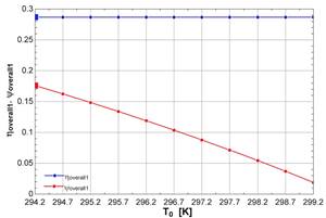
Fig. 4. Variation of reference temperature T0 – Energy and exergy efficiency
The energy efficiency is displayed with a blue line, the exergy efficiency with a red line. The results form section 6.2 are marked with a bigger dot.
With increase of the reference temperature T0 no change of energy efficiency is detected. The exergy efficiency is decreasing for higher reference temperature. A strong dependency of the exergy efficiency to the reference temperature is detected. A further increase of the exergy efficiency is limited by the components exergy efficiency of heat exchanger 30-1 and evaporator 30.
7.2 Temperature Carbon Dioxide Cycle
In figure 5 the overall energy and exergy efficiency for varying temperature T1 is shown.
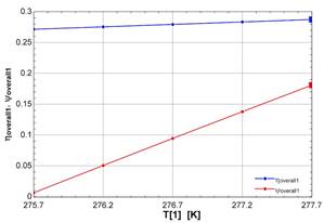
Fig. 5. Variation of temperature carbon dioxide cycle T1 – Energy and Exergy efficiency
The energy efficiency is displayed with a blue line, the exergy efficiency with a red line. The results form section 6.2 are marked with a bigger dot.
By increasing the temperature T1 of the carbon dioxide cycle, the energy efficiency increases slightly. A strong rise of the exergy efficiency for the temperature variation is detected. Its limited by the exergy efficiency of heat exchanger 30-1.
7.3 Mass Flow Water
Overall energy and exergy efficiencies at varying mass flow of the powerplant condenser mW are shown in figure 6.
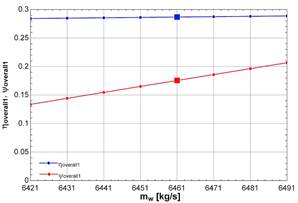
Fig. 6. Variation of mass flow water mW – Energy and Exergy efficiency
The energy efficiency is shown by a blue line, the exergy efficiency by a red line. The big dots mark the results form the calculations presented in section 6.2.
The energy efficiency is nearly constant for higher mass flows (0.1 % for ∆mW = 70kg/s). The exergy efficiency is increasing with higher mass flows. A higher exergy efficiency can’t be achieved due limits at the exergy efficiency of evaporator 30 and heat exchanger 30-1.
7.4 Mass Flow Carbon Dioxide
Figure 7 shows the influence of the mass flow in the carbon dioxide cycle mABC.
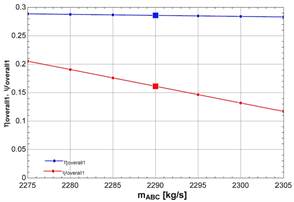
Fig. 7. Variation of mass flow carbon dioxide mABC – Energy and Exergy efficiency
The energy efficiency can be seen by a blue line, the exergy efficiency by a red line. The results form section 6.2 are marked with a big dot.
The energy efficiency is slowly decreasing with higher mass flows of carbon dioxide. The exergy efficiency is also decreasing for higher mass flows. It has a stronger dependence to the variation. Further variation is limited by the exergy efficiency of heat exchanger 30-1.
7.5 Mass Split Path A-B
Overall energy and exergy efficiencies for varying mass split of path A and B are shown in figure 8.
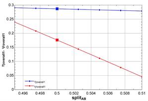
Fig. 8. Variation of Mass Split Path A-B splitAB – Energy and Exergy efficiency
The different energy efficiencies are displayed with a blue line, the different exergy efficiencies with a red line. Results from section 6.2 are marked with a big dot.
The energy efficiency is nearly constant for different splits of the mass flow of path AB. Exergyefficiency has a strong dependence on the split. It decreases for higher mass flows through path A. Further variation is limited by the exergy efficiency of heat exchanger 30-1.
8 Alternate Carbon Dioxide Cycle
In this section an alternate cycle and its results of analysis are presented. The reasonable assumptions are listed in section 8.2. The energy and exergy efficiency, the possible energy output and all other fluid data are calculated with the equations of section 3, 4 and 5. The results are shown and discussed in section 8.3.
8.1 System Description Alternate Carbon Dioxide Cycle (System2)
An alternate carbon dioxide cycle and its state points is presented in figure 9. In the rest of the report it will be referred as system 2.
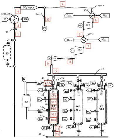
Fig. 9. Alternate carbon dioxide cycle (system 2) with state points of working fluid [1]
Instead of splitting up in three equal parts, system 2 is divided into 2 parts (Path A and C). Waste heat from the flue gases or from other processes of the powerplant are used to reheat Path A. The hole path B is eliminated as well as compressor 31 and liquid expander 31-2. All other components work as described in section 2.2.
8.2 Assumptions
The same assumptions for system components and state points were made to compare both system correctly. Further Assumptions are listed below.
– Heat from flue gases is used for reheating process
– New path A: same mass flow as old path A + B – Temperature of flue gas for reheating path A:
Tsource,HX301 = Tsource,HX301 = 600K
8.3 Results of Analyses
The alternate cycle (System 2) is calculated with the equations from section 3, 4 and 5. The assumptions from section 8.2 were used. The thermodynamic properties of each state point are listed in table 8.3.
T-s- Diagram
The carbon dioxide cycle (system 2) with the the calculated thermodynamic state properties is shown in a T-s- diagram for carbon dioxide (figure 10).
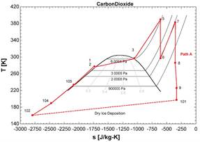
Fig. 10. T-s- diagram for alternate cycle
The state points of system 2 are connected by a red line.The dry ice deposition is shown by a small-dashed line.
Table 5. Thermodynamic Properties at Each State Point for the Carbon Dioxide Cycle System 2
|
State Point |
Path |
Mass Flow |
Pressure |
Temperature |
Specific Enthalpy |
Specific Entropy |
Specific Exergy |
|
– |
– |
kg s−1 |
Pa |
K |
J kg−1 |
J kg−1 K−1 |
J kg−1 |
|
1 |
AC |
2285 |
8.27E+06 |
277.6 |
-300303 |
-1734 |
210084 |
|
2 |
AC |
2285 |
6.21E+06 |
276.9 |
-300303 |
-1726 |
207733 |
|
3 |
AC |
2285 |
6.21E+06 |
297.3 |
-103007 |
-1054 |
207470 |
|
4 |
A |
1523.4 |
6.21E+06 |
297.3 |
-103007 |
-1054 |
207470 |
|
5 |
A |
1523.4 |
6.21E+06 |
390 |
46268 |
-606.4 |
224932 |
|
6 |
A |
1523.4 |
1.93E+06 |
297.3 |
-20373 |
-606.4 |
158291 |
|
7 |
A |
1523.4 |
1.93E+06 |
383.2 |
64471 |
-355.5 |
169350 |
|
8 |
A |
1523.4 |
517107 |
286.1 |
-15432 |
-355.5 |
89447 |
|
9 |
A |
1523.4 |
172369 |
226 |
-61210 |
-332.7 |
36952 |
|
10 |
A |
1523.4 |
172369 |
226 |
-61210 |
-332.7 |
36952 |
|
10.1 |
A |
1523.4 |
101353 |
197.5 |
-81985 |
-332.7 |
16177 |
|
10.2 |
A |
1523.4 |
101353 |
160.9 |
-534974 |
-2794 |
287102 |
|
10.3 |
A |
1523.4 |
101353 |
160.9 |
-534974 |
-2794 |
287102 |
|
10.4 |
A, Part of C |
1751.9 |
689476 |
189.7 |
-478630 |
-2474 |
249427 |
|
10.5 |
AC |
2285 |
8.27E+06 |
234 |
-390985 |
-2089 |
223692 |
|
10.6 |
AC |
2285 |
8.27E+06 |
277.6 |
-300303 |
-1734 |
210084 |
|
11 |
AC |
2285 |
8.27E+06 |
277.6 |
-300303 |
-1734 |
210084 |
|
12 AC 2285 8.27E+06 277.6 -300303 -1734 210084 |
|||||||
The reheating processes can be seen in figure 10.
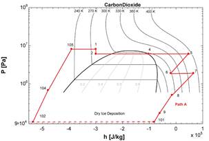
Fig. 11. p-h- diagram for alternate cycle
p-h- Diagram
The carbon dioxide cycle (system 2) is also shown in a h-p- All state points of system 2 are connected within the prodiagram (Figure 11) for a better understanding. cess. The dry ice process is displayed by a dashed line.
Exergy Efficiencies of System Components
The exergy efficiencies of the system components are listed in table 6. They were calculated with the formulas from section 5.2.
Table 6. Exergy efficiencies for system 2
|
System Component |
Exergy Efficiency [%] |
|
Evaporator 30 (ψevap) |
14.11 |
|
Heat exchanger 30-1 (ψHX301) |
22.95 |
|
Heat exchanger 30-2 (ψHX302) |
25.57 |
|
Turbine 32-1 (ψTurbine321) |
100 |
|
Turbine 32-2 (ψTurbine322) |
100 |
|
Turbine 32-4 (ψTurbine324) |
87.21 |
|
Venturi nozzle 36 (ψVN36) |
82.78 |
|
DT- Vessel 1 (ψDTV1) |
61.58 |
|
DT- Vessel 2 (ψDTV2) |
100 |
|
DT- Vessel 3 (ψDTV3) |
90.14 |
|
DT- Vessel 4 (ψDTV4) |
93.35 |
|
DT- Vessel 5 (ψDTV5) |
39.74 |
Isentropic processes, such as Turbine 32-1, Turbine 32-2 and DT-Vessel 2 have an exergy efficiency of 100 %. The process in Turbine 32-2 has an similar exergy efficiency as the isentropic efficiency for this process.
The exergy efficiencies for all processes in the DT- Vessel are high, the efficiencies for the heating processes Evaporator 30, Heat exchanger 30-1 and Heat exchanger 30-2 are low.
Energy and Exergy Efficiency of System The calculated values of energy and exergy efficiency are listed in table 7.
Table 7. Energy and exergy efficiency overall
|
energy efficiency (ηoverall) |
35.56 % |
|
exergy efficiency (ψoverall) |
14.31 % |
Other important parameters of the carbon dioxide cycle are listed in table 8.
Table 8. Important Parameters of System 2
|
T0 |
294.15 K |
|
p0 |
101353 Pa |
|
splitC |
0.3 |
|
Q˙evap,in |
450.8 MW |
|
Q˙HX301 |
227.4 MW |
|
Q˙HX301 |
129.2 MW |
|
W˙generator,overall |
287.1 MW |
9 Environmental Impact and Sustainability
As described in section2 and 8.1, both Carbon dioxide cycles are used in combination with other power plants to use the waste heat. The additional electrical power generation increases the overall power efficiency.
To make a system more sustainable, the given resources should be used more efficiently. Increasing the exergy efficiency of the system is the best approach and an important factor for an sustainable development [2].
The carbon dioxide cycle (system 1) uses waste heat form the condenser of a power plant. In normal operation this heat would be seen as loss to environment. The additional carbon dioxide cycle with an energy efficiency of 28.69% and an exergy efficiency of 17.61% increase the overall efficiency of the power plant a lot.
With the parametric study of system 1, even more efficient and sustainable operation strategies are presented (see section 7).
The alternate carbon dioxide cycle (system 2) also uses waste heat from the condenser of a powerplant. The waste heat from flue gases or other waste heat can be used for the heating process of path A (see section 8.1). By using even more heat sources, that would be accounted as loss in the normal process, this alternate cycle can be seen as more sustainable than system 1. The cycle energy efficiency of system 2 with 35.56% is higher than the energy efficiency of system 2. The overall exergy efficiency of system 2 (14.31%) is lower than the exergy efficiency of system 2.
Since less heat is provided to the surrounding, the environmental impact through heat pollution can be reduced. As mentioned in patent [1], cooling towers can be eliminated with this renewable cycle. The location of a new power plant would not longer be limited to a location with a cooling water resource [1]. All these factors would reduce the environmental impact of the power generation and would increase its sustainability.
This renewable energy system can not only be used in combination with a conventional power plant (as described in this report). It can be also used to rise the efficiency of other renewable energy systems, such as geothermal or solar sources [1].
10 Conclusions
All state points of the carbon dioxide cycle (system 1) are provided in section 6.2. The cycle is presented in a T-sdiagram and a p-h-diagram. Exergy efficiencies of all components are listed. The efficiencies in Evaporator 30 and Heat exchanger 30-1 and 30-2 are small and limit the exergy efficiency of the system. The overall energy efficiency is 28.96%, the overall exergy efficiency is 17.61%. To improve the operation strategy of the renewable energy system, parametric studies were made. The energy efficiency rises slightly for a higher process temperature of T1, a higher mass flow of the condenser water mW and a lower mass flow of carbon dioxide mABC. The exergy efficiency is more sensitive to parametric variation. A strong rise of the exergy efficiency can achieved by more mass flow of condenser water mW, less mass flow of carbon dioxide mABC and less mass flow in Path A (compared to Path B).
All state points of the alternate carbon dioxide cycle are also provided in section 8.3. A additional T-s- and p-h-diagram is presented. The exergy efficiencies of all components are also listed. The overall energy efficiency is 35.56%, the overall exergy efficiency is 14.31%.
To compare both systems 1 and 2 accordingly, no other changes than removing path B and all its components and adding heat supply though Heat exchanger 30-1 and 30-2 were made (see section 8.2). The overall energy efficiency of system 2 is higher. The exergy efficiency of system 2 lower than the exergy efficiency from system 1.
System 1 can be used in combination with any low heat source, such as a powerplant condenser, solar heat or geothermal heat. System 2 needs an additional heat source at higher temperature to reheat path A, which limits its field of operation. The cycle of system 2 has less components and therefore is more economical.
References
[1] SR. Calvin Eugene Phelps. Renewable energy process and method using a carbon dioxide cycle to produce work, U.S. Patent 2019/0170025 A1, Jun. 6, 2019.
[2] Ibrahim Dincer and Marc A. Rosen. Chapter 4 – exergy, environment and sustainable development. pages 51 – 73, 2013.
Cite This Work
To export a reference to this article please select a referencing stye below:
Related Services
View all


DMCA / Removal Request
If you are the original writer of this assignment and no longer wish to have your work published on UKEssays.com then please click the following link to email our support team:
Request essay removal