Computer Vision In Bad Weather.
| ✅ Paper Type: Free Essay | ✅ Subject: Computer Science |
| ✅ Wordcount: 1591 words | ✅ Published: 29 Mar 2018 |
Saswati Rakshit
Aim:
To take advantage of bad weather in estimation of depth of a scene from its image. As in bad weather atmosphere modulates original information of an image to the observer so based on observation,we develop model & methods for recovering scene properties(e.g. 3D structure,depth etc).
Scope/Application:
Computer Vision is widely used in various fields now a days.
It is used in Optical character recognition: Technology to convert scanned docs to text Face detection,Smile detection: Many new digital cameras now detect faces and smiles.
surveillance and traffic monitoring.
Image to a 3D model : turning a collection of photographs into a 3D model
Google Self driving Car uses computer vision for distance estimation
Introduction :
Vision and Atmosphere:
Normally in good weather we assume reflected light passes through air without attenuation.so it is assumed brightness of an image point in the scene will be same.But due to atmospheric scattering,absorption and emission light intensity and color are altered. Here our main consideration is on scattering.
Bad weather(Particles in space):- weather condition differ in type and size of particles and their concentration.
Air (molecule): scattering due to air is minimal
Haze (aerosol): haze is certain to effect visibility.
Fog (water droplet): Fog and haze has similar origins.but haze extends to altitude of several miles while fog is few hundred feet thick.
Cloud is present in high altitude.
Rain and snow both effects in image.
Here our main consideration is on haze and fog because they appear in low altitude as compared to cloud.
Mechanisms of atmospheric scattering
Scattering is dependent on particle size and shape.small particles scatter equally in forward and backward,medium size particle scatters more in forward direction and large particle scatters all in forward direction.
In nature particles are separated from each other so they scatter independently.i.e. do not interfere others.but In multiple scattering a particle is exposed not only incident light but also light scattered by other particles.
Single scattering function can be written as follows
I(Ó¨,λ)=E(λ).β(Ó¨,λ) ————————————————(1)
Where E(λ) is total incident flux on the volume per unit cross section area
I(Ó¨,λ) is flux radiated per unit solid angle per unit volume of medium and β(Ó¨,λ) is the angular scattering coefficient
Objectives: To identify effects caused by bad weather that can be turned to our advantages.understanding attenuation and airlight model that is helpful to measure depth maps of scenes without making assumption about scene properties or the atmospheric conditions.
System flow:
Here our main goal is to estimate depth and forming 3D of a scene in bad weather condition.
For this purpose we used Two different scattering model
1) Attenuation model
2) Airlight model
Now first we have used attenuation model and In this model image is taken at night.so environmental illumination are minimal. To estimate depth of light sources in the scene from two images taken under different atmospheric conditions.
And applying different mathematical formula used in attenuation model we can compute relative depth of all sources in the scene from two images taken under two different weather condition.
Next to work with airlight model we need images in day or when environmental illumination can not be ignored.that is image of a scene is effected by airlight.
After selecting the 2D image we apply mathematical formulas of airlight model and comparing the intensity of scene point depth can be easily measured an 3D reconstruction of that scene is also possible.
Mathmatics And Description:
Attenuation Model
We know that beam of light that travels through atmosphere can be attenuated by scattering.and the radiance(intensity) decreases if pathlength increases.
Attenuation model developed by McCartney is summarized below
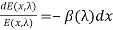
If a beam passing through a small sheet(medium) of thickness dx, intensity scattered by the sheet can be written as follows
I(Ó¨,λ)=E(λ).β(Ó¨,λ) dx
[it represents scattering in Ó¨ direction]
Now total flux scattered in all direction is obtained by integrating over entire spherical sheet
φ(λ)=E(λ).β(λ) dx ———————————————-(2)
fractional change in irradiance at location x can be written as follows:
 ———————————————-(3)
By integrating both side of eqn(3) between limits x=0 and x=d we get
E(d, )=
)= ————————————-(4)
Where I0(λ) is the intensity of the point source and d is the distance between object and observer’
Sometimes attenuation due to scattering can be expressed in terms of optical thickness which is
T=
[here  is constant over horizontal path]
Here eqn (4) gives direct transmission which we get after removing scattered flux.
Airlight Model
Here atmosphere behaves as source of light.environmental illumination has several light sources including direct sunlight,diffuse skylight and light reflected by the ground.In airlight model light intensity increases with pathlength and so apparent brightness increases. If the object is in infinite distance the radiance of airlight is maximum and radiance of airlight for an object right in front of the observer is zero.
To describe the geometry of that model,first we need to consider environmental illumination along the observer’s line of sight is assumed to be constant but direction and intensity is unknown.
Let the cone of solid angle dω subtended by a receptor at observer end.and truncated by the object at distance d.
This cone between observer and object scatters environmental illumination in the direction of observer.so it acts as airlight(source of light) whose brightness increases with pathlength.
So the small volume dV at distance x from observer is dV= dω x2 dx
Now the intensity of light incident on dV is
dI(x, )= dV k = dω x2 dx k ………………………………………(5)
now light scatters in dV.so irradiance it produces at observer end is
dE(x,) = ………………………………………….(6)
[also given in eqn (4)]
Now we can find radiance of dV from its irradiance as:
dL(x,) = =
=  …………………………………..(7)
by substituting (5) we get, dL(x,)=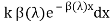
now we will find total radiance of pathlength d from observer to object by integrating the above expression between x=0 to x=d
L(d,)= k (1- ) …………………………………………….(8)
If d =∞ the radiance of airlight is maximum L(∞, =k
=k
So , L(d,)= L(∞, (1-) …………………………………………(9)
Estimation of depth using Attenuation Model:
In this model image is taken at night.so environmental illumination are minimal and so airlight model is not chosen.At night bright points of image are normally street light,windows of lit rooms.In clear night these light sources are visible to observer in brightest and clearest form but in bad weather condition the intensity diminish due to attenuation.
Our goal is to estimate depth of light sources in the scene from two images taken under different atmospheric conditions.
Here image irradiance can be written using eqn(4) as:
E(d,)= g ————————————————–(10)
[g is optical parameters of camera]
If the detector of the camera has spectral response s(λ),he final image brightness value is
E/=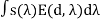 =
= —————————————(11)
We know spectral bandwidth of camera is limited so we can assume  as constant.
And we can write,
E/=g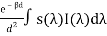 =g
=g I/ ————————————————–(12)
Now if we take image in two different weather condition i.e. in mild and dense fog then there will be two different scattering coefficient. Let it will be β1 and β2.now if we take ratio of two resulting image brightness we get
R= =
= —————————————-(13)
Using natural log R/=ln R= ……………………………..(14)
This ratio is independent of camera sensor gain and intensity of source.
In fact it is only difference in optical thickness(DOT) of the source for two weather conditions.
Now if we compute the DOT of two different light source and take the ratio we determine relative depths of two source locations
So we can write,
 =
= …………………….(15)
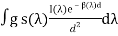
Since we may not entirely trust the DOT computed for any single source.so above calculation can be made more robust
 =
=  ……………………………………..(16)
[here we assume to find the intensity of a single source pi,which is at distance di from observer.so to calculate its relative depth from other sources we need to compute depth of all sources of the scene upto a scale factor]
The main goal of using this model is to compute relative depth of all sources in the scene from two images taken under two different weather condition.
Estimation of depth using Airlight Model:
At noon or daytime in dense haze or fog or mild fog most visible scene points are not illuminated and airlight effects.airlight causes intensity to increase when distance increases.
Here we consider a single airlight image and try to compute 3d scene structure by measuring depth cues.
Let,a scene point is at distance d and produce airlight radiance L(d,).if our camera has spectral response S(
The brightness value of that scene point is:
E/(d)=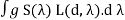 ………………………………………………………………………….(17)
Substituting it by eqn (9),we get
E/(d)= …………………………………………………………(18)
If is constant we can write,
E/(d)=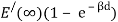 …………………………………………(19)
Now Let,
S= …………………………………………………(20)
By substituting eqn(19) at eqn (20),and taking natural logarithm we can write,
S/= ln S = -βd ………………………………………………………………(21)
Here S/ is scale factor and a 3D structure of scene can be recovered upto this scale factor
The part of horizon in the image which has intensity  will be the brightest region of the image.(sky background)
Future work:Next we will understand and discuss about Dichromatic Atmospheric Scattering and structure from Chromatic Decomposition.
References:
Cite This Work
To export a reference to this article please select a referencing stye below:
Related Services
View all


DMCA / Removal Request
If you are the original writer of this essay and no longer wish to have your work published on UKEssays.com then please click the following link to email our support team:
Request essay removal