The Structure and Use of 3D Models
| ✅ Paper Type: Free Essay | ✅ Subject: Design |
| ✅ Wordcount: 4496 words | ✅ Published: 29 Aug 2017 |
Guide showing the structure and use of 3D Models
Topic 1 Structure of 3D models
3D coordinate systems
Explain – There are two types of coordinate systems that are commonly used in 3D graphics, either left or right handed, in both coordinate systems both the positive X and Y axis are the same with the Z axis being the only main difference.
Analyse
World – The world coordinate system also known as universe or model coordinate system is the base reference for the overall model, all other models relate to.
Local – The local coordinate system relates specifically to a selected object when the object moves the local axis will move with is making it easier to animate. The local space has a completely separate xyz from the world/global xyz.
Z-up – Is one of the ground axis and is used to say how far a model is moved left or right depending on the number given.
Y-up – Is the up/elevation axis and is used to determined where a model is placed when moved either up or down depending on the number that is given.
Evaluate – the 3D coordinate system is extremely helpful as it gives us a visual reference on where an object/model would be in the 3d world. This allows us to position models exactly where we need them.
Views of 3D models
Explain – There are two ways we can look at 3d models either perspective or orthographic, they are used to see the 3d model in either the view of the user (perspective) or as a flat 2d image (orthographic).
Analyse
Perspective – Perspective is an approximate representation of an image as seen by the user’s eye, the most characteristic feature of perspective viewing are that objects appear smaller the further away as the distance from the object and observer increases.
Orthographic – Orthographic view has a fixed depth in which you cannot zoom in or out, and is used when checking if different models at different depths are the same size, this is done by making the models appear 2d.
Evaluate – both views have their advantages and disadvantages, where the perspective view can help you view the models/objects in a way that is natural to the human eye it doesn’t help when you’re trying to match the height of distant objects, whereas using the orthographic view allows you to see all objects as a 2D image allowing you to scale objects to the correct size.
The Geometric Structure of Models
Explain -Â 3D models are mathematical representations of an object, they can be compared to sculpting as a 3D artist would build or mold the object by taking into account all the sides and angles. The elements that make a 3D model consist of vertices, edges, faces and polygons, all of which can be manipulated individually in whichever software you choose such as blender, Maya or 3D studio Max.
Analyse
Vertex – Vertices are the smallest point of a 3D model, they are made when two or more edges meet therefore corners of the polygons fuse together to make a vertex. The vertex is shared between all edges, faces and polygons and would affect all of these if the vertex is transformed.
Edge – The edge in a 3D model is a line which connects two vertices and borders faces and polygons, transforming these will affect all vertices faces and polygons which are connected to the edge.
Polygon/face – Face is a triangular surface connected by three surrounding edges and three corner vertices where as a polygon is an even four surface made up of four or more corners and two or more faces, high quality 3D characters are usually made of four sided polygons as ones with five or more sides can cause issues.
Element – the elements of a model are as follows tets, bricks, prisms, and pyramids these can be used to mesh any 3D model, with the 2D equivalents being triangular and quadrilateral elements.
Surface normal – modifying the orientation of surface normals affects the polygons appearance, when the surface normals are at right angles to a face light appears to bounce off the surface, this sharply defines the polygon face creating crisp edges, when set at different angles this allows light to roll off, which creates a smoother look.
Evaluate – knowing the structure of a model can help in deciding which shapes to start from and also to help manipulate the shape into the desired model/ object that you are looking for.
The Structure of Different Polygons
Explain – There are three different ways of creating a mesh either using triangles quads or n-gons, tris and quads are more preferable than and n-gons are just avoided at all cost as they can cause issues.
Analyse
Triangles – Triangles are a simple three sided polygon,made of three vertices connecting three edges, it is the smallest configuration needed to make a polygonal face. Also referred to as a tri.
Quads – Quads are the most desired type of polygon and most artist would use only quads as it makes their work more appealing to customers. They are made up of exactly four sides and four vertices, quads can also be referred to as quadrilateral polygons.
N-gons – N-gons are made up of more than four edges and vertices, n-gons can usually be divided into either quads or triangles or sometimes both which makes them easy to replace. They are usually avoided as they often create unwanted topology.
Evaluate – Using tris quads is very well sought after as theses are what computers can render them a lot faster especially quads, ngons on the other hand are usually avoided as they tend to cause distortion and deformation, tris can also cause this issue but not as much.
Different methods of creating models
Explain – There are two different ways of creating models either with polygonal modeling or spline/curve based modeling, these are both used to create models with polygonal being the most used as it is more flexible but curve-based will make smoother curves.
Analyse
Polygonal modeling – Polygons are created by using points in a 3d space called vertices, when they are connected together they form a mesh, which is used mainly for 3d models as they can easily be manipulated and rendered by computers quickly. On the downside they are planar and can only estimate a curved edge based on many polygons.Â
Spline/ curve-based modeling – Curves are based off weighted control points, which when increased influences the curve closer to that point. The curve follows but does not always enter the points. Curve types include splines, nonuniform rational B-spline (NURBS), patches and geometric primitives.
Evaluate – The different methods in modeling be it polygonal or curved based both have different advantages and uses depending on what is needed, polygonal modeling is best used for 3D models as they can be rendered quickly by computers but the downside is that they are planar and can only make rough curves. Curve Based on the other hand is best used in a situation where curves and edges must be as smooth as possible such as in engineering, although manipulating it can be a lot harder.
Pivot points
Explain – Pivot points are used to represent the location of a model in space, they are also used to control how models rotate and scale and move. All changes to a model are relative to the pivot point.
Analyse -Â
Move – moves the pivot point bringing the object that is connected to the pivot point with it.
Scale – increases or decreases the size of the object from the point of the pivot origin.
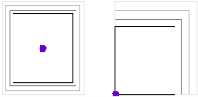
Rotation – rotates the object/model around the pivot point depending on the postion of the pivot point.
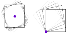
Evaluate – Having a movable pivot point is advantageous as it allows the object to be moved, rotated and scaled from different points allowing you to manipulate the object in many ways.
UV coordinates
Explain – Are 2D coordinates used on a 3D model and are basically a textures x and y coordinates which always range from 0 to 1. With the V value going from bottom left to top left and the U value going from bottom left to bottom right, each vertex will have a uv coordinate value.
Analyse -Â UV mapping is usually done by unfolding a model, a pyramid for example, at the seams laying the model image onto a flat page once unwrapped the artist can then paint a texture onto each side triangle individually.

Evaluate – Allows for more detailed texturing and painting on 3D models by assigning pixels in the image to surface mappings on the polygon, this can then be easily exported to other 3d programs and then further adjusted.
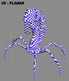
Mapping methods
Explain -Â Mapping methods are ways in which textures are applied to different models and objects, they are mainly used to quickly apply a texture to different shaped models depending on what the model shape is as some work better than others.
Analyse
Planar – planar is used to apply a texture onto a flat model such as basic terrain and walls, when trying to place a texture on an uneven or complex surface it can often stretch and distort polygons that are not facing the projected map directly.
http://www.gamasutra.com/view/feature/130484/uv_mapping_tips_and_tricks.php
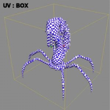
Box – box mapping is done by placing a texture onto a model from six different sides, which is mainly used when you need quick mapping for less important of a model, and also used on technical or architectural objects. It is however not as useful for texturing more natural models where more accurate mapping is required.
http://www.gamasutra.com/view/feature/130484/uv_mapping_tips_and_tricks.php
Cylinder – Cylindrical mapping is used for mapping more cylindrical models such as arms, cans and trees, it is one of the most used type of mapping but still needs tweaking afterwards in the uv editor.
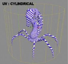
http://www.gamasutra.com/view/feature/130484/uv_mapping_tips_and_tricks.php
Spherical – Spherical mapping is mainly used to map out asteroids and planets, one downside is that it causes pixels to compact at the poles of the sphere. It can be used to block out mapping on human heads but loses its usefulness on models with multiple overlapping parts. Requires significant work afterwards.
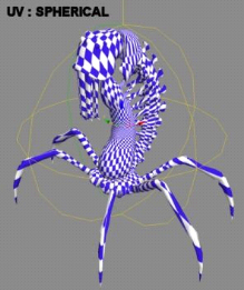
http://www.gamasutra.com/view/feature/130484/uv_mapping_tips_and_tricks.php
Unwrapping – unwrapping is done by creating uv coordinates which is generated for each vertex. One way is for the 3d modeler to unfold the mesh at the seams laying the model on a flat page, once unwrapped you can then paint a texture on each individual polygon.
Pelt – pelt mapping is used to map more natural models like animals and characters, pelt mapping allows you to pull a detailed uvw map flat allowing you to make a more accurate shape of the model which makes it easier to produce a more convincing texture.
Evaluate – Most mapping methods are extremely useful as they allow you to map a texture onto the different surfaces of a model as there are multiple choices to pick from there is usually one to fit the model you are working on, theses can save a great deal of time by quickly mapping the texture onto oddly shaped models which would be time consuming otherwise.
The materials used on 3D models.
Explain – Adding textures to models is a lot more than just adding colours, you are also able to use different techniques and mpas to add more detail to the model letting you add effects such as shadows textures height etc.
Analyse
Base Colour, Albedo, Diffuse -Â is the most common texture map, it specifies the
pattern and colour of the object. It basically paints an image onto the surface.
Normal Maps – a normal map is a map which defines the direction your geometry normals are facing, with this info you can create a fake the illusion of height to how the model is affected by light.
Height Maps / Displacement Maps – displacement maps are used when you need to add more detail to affect your model, this is a very powerful option as it actually affects the geometry.Â
Ambient Occlusion – The occlusion map is used to define the areas of a model which should receive low or high indirect lighting. It is a grayscale image with white marking areas which should get full indirect light, and black for areas receiving no indirect light. An example would be a stone wall texture which is uneven.
Specular Maps – Specular mapping is used to define how well an area reflects light, the colour and bumpiness may be the same but using either dark or light tones you are able to change how reflective the surface is. An example would be a characters eyes compared to the skin or how a material reacts when wet or dry.
Lightmaps – are data structures used in light mapping, it works by pre-calculating the brightness of a surface and storing it in texture maps for later use. They are more used on static items so as the light does not need to be recalculated every frame.
Evaluate – using these can be extremely helpful in creating the models you desire without having to form the whole thing as some can help create the effects of textures, shadows height, and even make them seem more detailed which saves you adding more polygons to a model and increasing the count.
http://blog.digitaltutors.com/understanding-difference-texture-maps/
The creation and use of convex collision hulls.
Explain – A convex collision hull is a simplified low poly count meshes that encases more complex objects, this is used to determine where a collision will occur on the object as well as other physic based interactions.
Analyse – It is an invisible mesh that stops the player and other models falling through each other, this can be costly on the graphics and processor power as the model triangles have to be calculated twice, once for the 3d model and once for the mesh collider. Each object must have a collision shape. Simpler shapes such as boxes, spheres and capsules are used as they are much faster to test but are less precise.
Evaluate – the collision hull helps make objects and models seem more to life by not letting you fall through walls and floors but can also affect how some objects are effected depending on how simple or complex the hull is compared to the model it is covering.
Level of detail models (LODs)
Explain – LODs or level of detail are used to help render times by reducing the amount of polygons that show on models which are further away from the character, this is used to help rendering times and helps performance.
Analyse – LODs limit the amount of polygons on a model to help reduce rendering times whenever the character is at a distance, this helps keep focus on the immediate area and less at background scenery.
Evaluate – LODs can help increase frame render time by reducing the amount of polygons and detail that is on screen at any one time by determining what’s more important or what’s being focused on more and only giving that the proper amount of detail. Although this can help render time it may also cause some lag or drop in frames when too much detail is trying to load in at once.
Vertex colour information
Explain – Vertex colour is a RGBA value that is traditionally used to add diffuse or emissive colour to the geometry of the model, this can be added to any vertex on the model. With more powerful games engines this can be used to do amazing things.
Analyse – Vertex colouring is used to colour foliage animations, baking inexpensive AO and lighting info, it can also be used to blend different materials on terrain or other meshes, but can be used for a lot more things
Evaluate – Vertex coloring can be used easily as it requires no UVs, although it is geometry dependant and not suited for high detail.
Model constraints
Explain – When creating content such as 3D art for games and other real time applications there is constrictions which need to be applied to help increase performance and reduce render time. These constraints include polygon count, texture size and file size.
Analyse –
Polygon Count – The constraint on polygons count is that the more polygons or faces that appear within the render view the longer it takes for the frame to render, this limits polygons count to help with rendering time. This applies to games as well as non real time animations or special effects, this is all linked to the hardware available.
Texture size – textures need to be done effectively as the bigger and more complex the texture the longer the game will take to load it, this can cause the textures to take time to render and ruin the experience of the player.
File Size – The two main constraints that file size has is that 3D graphics need to be stored somewhere, either on disc a hard drive or in the cloud waiting for digital download. For this reason file size needs to be efficient to make sure they fit onto the the media that they are designed for, if the 3D art is too large for one disc it must be split onto two or more discs or may require an extremely long time to download especially for those with slow internet speeds.
Evaluate – Model constraints help with loading and rendering times by limiting the amount polygons and textures the artist is allowed to use, although this seems bad if there was no constraints the game would not load well and have constant drops with the frame rate, the downside to this is that the game will unfortunately not have everything that the developers wanted as some things may need to be cut due to file size restrictions.
Topic 2 Uses of 3D models
Decorative meshes
Explain – Decorative meshes are used to decorate a blank 3D world and make it more interesting, theses decorative meshes can range from indoor items such as chairs tables etc, to outdoor objects such as cars, trees and wells for example. Decorative meshes also help to make the 3D world seem a lot more interesting and also help make it more true to life and improve the player’s experience.
Analyse – these consist of multiple objects such as cars, trees, bushes etc which is placed around the 3D world so as it’s not blank and more interesting.
Evaluate – The advantage of using decorative meshes is that it increases the realism of the world they’re placed, they also improve the player’s experience as they are not walking around a bland world.
Environment meshes
Explain – Environments are what a 3D world is made from, every environment also needs to be filled with 3D meshes, a balance of quantity and quality must be found as this needs to be as good looking as possible but also needs to be done efficiently.
Analyse – Environment meshes are used to create the 3D worlds invitroment, be in be buildings or other structures, this needs to be able to be done effectively and quickly as it’s a main part of the world but not all the focus will be on it.
Evaluate – Allows for a more immersive world as it adds character to the area and can also set the mood depending on the art style used.
Modular meshes
Explain – Modular meshes for 3D environments are used to create fast environments using small tiling models and maximum flexibility, to make this as effective as possible you should first make sure that the grid for the 3D package is the exact same as the grid that the engine you’re going to make the model for. Modular meshes can be reused to save time on developing multiple models.
Analyse – modular meshes can be made into kits, for example piping for walls, so that the developers and artists can reuse them to speed up the process without putting in as much work for areas that require less attention.
Evaluate – the advantage of using modular meshes are that you are able to quickly create game environments with maximum flexibility to change when needed, they are also reusable meaning you can keep a certain art style no matter the size. The downside to this is that the reused art style can quickly become repetitive.
Meshes used for non-skeletal animation
Explain – Games can have a number of models which can be used for non skeletal animation these tend to be models which are not rigged (i.e with a skeleton) examples of these can be doors, boxes with lids that open, shop signs and even platforms can be animated to move.
Analyse – non skeletal animation works by the object or model not having a rigged skeleton allowing it to move or swing freely, for example a door may swing on its hinge, to create this the pivot point of the door must be placed at the point in which you want the door to swing.
Evaluate – the advantages of non skeletal animation are that it allows the game world to flow more freely using swinging doors, and makes the game seem more life like having signs and lids able to open.
Skyboxes and skydomes
Explain – A skybox is made from a cube with six images that inclose the player, they can also be known as environment maps. The player is placed in the middle of the box so that no matter which way they look they just see different parts of the box. The game engine makes sure that whichever part of the box is visible to the player the proper pixels are shown. Sky domes work in similar ways but is a 3D sphere or hemisphere, and can be animated to improve realism. Both the skybox and skydome usually has a texture of the sky on it depending on the game and what’s needed.
Analyse – skyboxes are simple cubes which consist of fewer polygons than the skydome, no matter where the player is they will always see the relevant part of the skybox.
Skydomes are more detailed as they contain more polygons and allow the maker to animate it to improve the realism of the 3D world.
Evaluate – the advantage of using a skybox is that it uses up less polygons and if easier to texture, although it does not look as good as a skydome. The skydome on the other hand allows you to use vertex colour you adjust the hue in a smoother way, this allows you to animate the sky depending on the time of day.
Rigid bodies
Explain – Rigid bodies allow your models and objects to act under the control of physics, the rigid body can be given forces and torque to make it move in a more realistic way. Any objects you wish to be influenced by physics or other added forces must have a rigidbody.Â
Analyse – rigid bodies can be affected by different physics such as:
Mass – This determines the weight of the object usually in kilograms by default
Drag – Drag determines how air resistance affects the object while moving (from 0 air resistance to infinity meaning it stops immediately)
Gravity – Determines if the object is affected by gravity if dropped for example.
Evaluate – Rigid bodies are extremely useful when wanting to make a game which either has real to life physics or if you want to make the game with wacky physics as you are able to mess with the properties of each.
Fracture/breakable meshes
Explain – Fracture or breakable meshes are used to make in game objects breakable for example doors, walls and in some cases building can also be destroyed, this can help the game feel more realistic as it adds real world physics to the game, it can also add new things for players to try out and in general make the game more fun. This can be broken down into more points such as chunk count and modify points.
Analyse – Chunk count determines how many chunks the tool will cut the original mesh into, a large amount of pieces means there’s more triangles in the final object and more pieces that will be left behind after. A smaller amount means there are fewer triangles and less pieces after the object is destroyed.
The modify points tool can be used to move the selected or all the chunk origins towards the bounds of the object or perturb some or all of the chunks in the slice pattern moving the pieces towards the bounds is useful as it helps avoid chunks being discarded because they dont slice the surface of the mesh.
Evaluate -Â Breakable meshes are used to help make games more realistic by letting you destroy some of the environment or some objects/models like you could in a real world situation. This however can have drawbacks on render time and frames as it requires more polygons to make the broken pieces.
References
() 3D Modeling: Creating 3D Objects, Available at: https://www.sculpteo.com/en/glossary/3d-modeling-definition/(Accessed: 6th October 2016).
() Collision Meshes & Game Models, Available at: http://www.katsbits.com/tutorials/blender/collision-models.php(Accessed: 8th October 2016).
() Fractured Static Meshes, Available at: https://udn.epicgames.com/Three/FractureTool.html (Accessed: 4th October 2016).
() Rigidbody, Available at: https://docs.unity3d.com/Manual/class-Rigidbody.html (Accessed: 11th October 2016).
(2014) 3D Constraints, Available at: https://docs.google.com/document/d/1cJlmKMQXiCHPX1zRKV3K1biO4EwH13_WOIt_8BJ7K6g/edit#(Accessed: 16th October 2016).
(2014) The pivot point, Available at: https://knowledge.autodesk.com/support/maya/learn-explore/caas/CloudHelp/cloudhelp/2015/ENU/Maya/files/Transforming-objects-The-pivot-point-htm.html (Accessed: 10th October 2016).
(2016) 3-D Coordinate Systems, Available at: https://msdn.microsoft.com/en-us/library/windows/desktop/bb324490(v=vs.85).aspx (Accessed: 2nd October 2016).
(2016) 3D coordinates, Available at: https://knowledge.autodesk.com/support/maya/learn-explore/caas/CloudHelp/cloudhelp/2016/ENU/Maya/files/GUID-FDC58F4E-63B9-4012-B232-5F2FBAC5EAC9-htm.html?v=2016(Accessed: 4th October 2016).
(2016) Level of Detail, Available at: https://docs.unity3d.com/Manual/LevelOfDetail.html (Accessed: 14th October 2016).
(2016) Perspective (graphical), Available at: https://en.wikipedia.org/wiki/Orthographic_projection (Accessed: 3rd October 2016).
(2016) Perspective (graphical), Available at: https://en.wikipedia.org/wiki/Perspective_(graphical) (Accessed: 3rd October 2016).
(2016) UNDERSTANDING UV MAPPING, Available at: http://www.steves-digicams.com/knowledge-center/how-tos/video-software/understanding-uv-mapping.html#b (Accessed: 6th October 2016).
Banninga, R (2004) UV Mapping Tips And Tricks, Available at: http://www.gamasutra.com/view/feature/130484/uv_mapping_tips_and_tricks.php(Accessed: 14th October 2016).
Bell, G () Creating Backgrounds for 3D Games, Available at: http://www.gamasutra.com/view/feature/131701/creating_backgrounds_for_3d_games.php?print=1 (Accessed: 10th October 2016).
Cahill, P (2016) 3D Modelling Basics & Terminology3D, Available at: http://www.onlinedesignteacher.com/2014/07/3d-modelling-basics_33.html (Accessed: 6th October).
Cole, T.B (2015) VERTEX COLOUR, Available at: http://www.timbencole.com/vertexcolour (Accessed: 11th October 2016).
Dennis (2007) UV coordinate basics, Available at: http://www.rozengain.com/blog/2007/08/26/uv-coordinate-
Cite This Work
To export a reference to this article please select a referencing stye below:
Related Services
View all


DMCA / Removal Request
If you are the original writer of this essay and no longer wish to have your work published on UKEssays.com then please click the following link to email our support team:
Request essay removal