Design of Search and Rescue Helicopter
| ✅ Paper Type: Free Essay | ✅ Subject: Engineering |
| ✅ Wordcount: 4047 words | ✅ Published: 30 Aug 2017 |
 Proposal:Search & Rescue Helicopter
This report highlights the design process of a S&R Helicopter system that can rival the competitors in the current market. In order to do so SysML modelling methods have been used to allow us to get a better understanding of the system and the problem at hand. To do so further research was conducted on the leading S&R Helicopter in the market, to get an understanding of what type of features are expected from the system. After conducting some requirements capturing, key design features are created for the S&R Helicopter. This is done by refining the requirements given to us by the customer/stakeholders. Engineering characteristics are then found from the key design features and represented in the association matrix. This leads on to tradeoff decision that need to be made to optimize the system and satisfy majority of the requirements given by the customer/stakeholders.
Systems Design for Helicopters
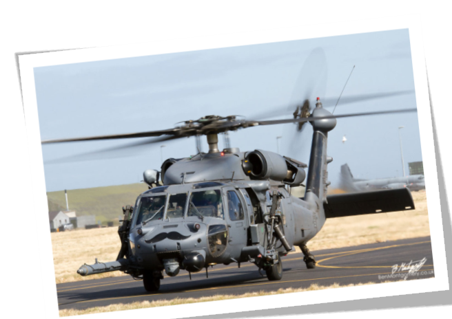
Through this report, we will develop a system design for a military search and rescue helicopter (S&R Helicopter) that can be used in missions that is in hostile environments. Following on from this we will conduct a competitive analysis of the designed helicopter to its competitors. The baseline for the new system will be using an existing military helicopter, the HH-60G.
1.1 Background of the HH-60G Pave Hawk
The primary mission of the HH-60G pave Hawk helicopter is to recover personnel from hostile environments. In addition, the helicopter also executes search and rescue, medical evacuation, disaster relief, security cooperation, NASA space shuttle support and rescue command and control missions [1].
The HH-60G Pave Hawk has been used in the past for several operations, including the Operation Desert Storm, Operation Allied Force and many more [1]. They have also been used to provide emergency evacuation for U.S. Navy SEAL teams in their operations overseas [1]. HH-60G Pave Hawk has not just been used for military operations but also for helping when natural disasters happen. For example, when there was an earthquake and tsunami in Japan, these helicopters were deployed to provide search and rescue within 24 hours of the disaster [1]. This illustrates how resilient these helicopters are already, so using this as the baseline of the system will ensure that the new system will have a solid foundation.
1.2 Aims
The aim of this report is to use system design modelling tools to design and analyse a search and rescue helicopter that met the customers’ requirements.
1.3 Objectives
- Conduct some background research on the current systems in the market
- Refine the requirements given by the customer/stakeholders.
- Use SysML tools to design and analyse the system.
1.4 Further research
Current Features on the HH-60G Pave Hawk include:
- communication and navigation that includes integrated navigation, global positioning and Doppler navigation systems [2] [1]
- Satellite communications [1]
- Secure voice and Have Quick communications [1]
- Can fit up to 12 troops and six crewmen onboard [1]
- Automatic flight control systems [2] [3]
- Night vision goggles [3]
- Infrared system that allows the pilot to see in low level light (limited visibility) operations [3] [1]
- Weather radar [1]
- Anti-ice system on the engine and rotor blades [2]
The HH-60G Pave Hawk includes equipment such as retractable in-flight refuelling probe, 7.65mm or 50calibre machineguns and a 3600kg capacity cargo hook. As well as a cargo hook the Pave Hawk also has a hoist cable that is capable of lifting a load up to 270kg from 200 feet [1].
Most of these features are upgraded from the UH-Black Hawk. Which just shows how the HH-60G Pave Hawk is the leading S&R Helicopter in the market in this moment in time.
2.1 Narrative
A military search and rescue helicopter’s (S&R Helicopter) purpose is to be a quick responder to finding a missing person or people. Naturally it will mean that the helicopter will have to travel at great speeds to reach the area that the missing personnel is assumed to be. But sometimes the mission commander (person who is in charge of the search and rescue mission) will receive new information on the location of the missing or injured people, which will then need to be relayed to the crew in the helicopter. Once the crew reaches their destination they need to have the technology onboard the helicopter that will allow them to locate the missing or injured person/people. This ranges from night vision goggles to radio systems. In some circumstances the missing people will have radios on them, which can be used to hail the helicopter. When the person or people are located the helicopter must be able to retrieve them from any terrain and have the space to accommodate them. In addition the helicopter will be tasked to go into hostile environments, which can put the crew and the helicopter it’s self through a lot of stress. The stress could range from subzero temperatures, storms and even bullets in a warzone. Usually the helicopters will be armed with weaponry that will defend its self from incoming fire from the ground and air.
2.2 Use case Diagram
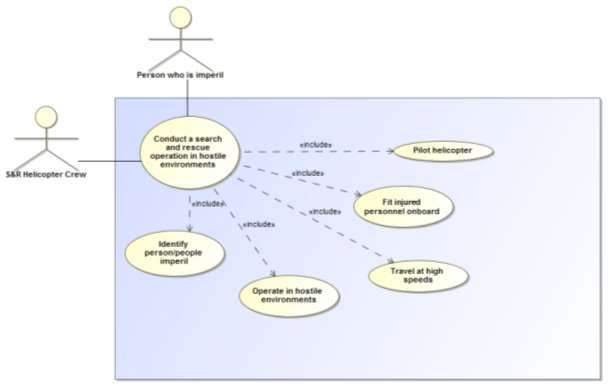
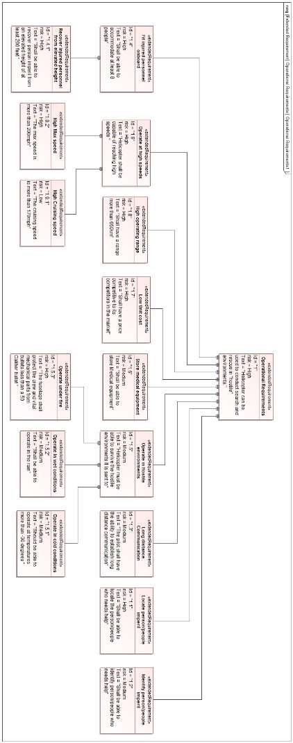
The use case diagram is used to allow us to identify the key requirements in the system. In addition, due to the fact that this use case is used for behavioural modelling, it allows the user to identify actors, relationships and the system boundary of the system. You can see in the figure 1 that there are multiple actors (stick figures) involved with this system. Initially there is a lot more but they are out of our scope in this moment of time. The use case in figure 1 starts off with the operational requirement, which is “Conduct search and rescue in hostile environments”, which then branches of into 4 other essential requirements such as “Operate in hostile environments” and “Travel at high speeds”.
Moving on, another use case diagram was created, as seen in figure 2, which highlights the remaining functional requirements. At this stage, the use case method sometimes highlights requirements that are derived from each other. For example, from “Identify person/people imperil”, three other requirements were derived; “Identify personnel at night”, “Long distance communications” and “Identify personnel in low visibility conditions”.
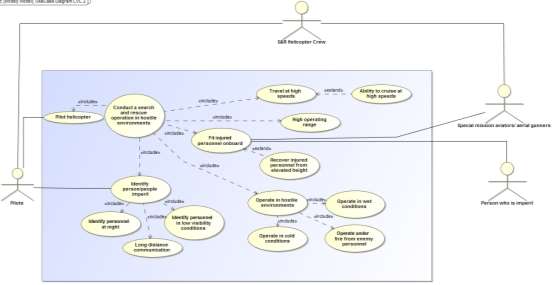
The next stage will be to identify all the different requirements and sort them into functional and non-functional requirements.
2.3 Requirements Identification
A systems engineer will use requirements to validate the stakeholders’ needs are satisfied by the delivered system [4]. Therefore a systems engineer should be able to understand the problem in different layers of perception [4]. Requirements identification also helps the systems engineer to check if he is creating the right system for the stakeholder.
2.4 Organise the requirements by Type
The requirements start off with an operational requirement, which highlights the highest level. Usually the operational requirement would be agreed with the primary stakeholder which is derived from the narrative provided earlier on in the report. As well as the operational requirements, the functional and non-functional requirements are then also derived from the narrative. To do this, the narrative is re-written a couple of times, refining the information till the engineer has a set of functional and non-functional requirements [5]. It is essentially an iterative process where the system engineer continuously analysis the requirements and refines each requirement until there is no ambiguity in them. These refined requirements are illustrated further down in the report, in 2.5 Requirements Model.
For this scenario, the Operational requirement would be:
- Conduct a search and rescue operation in hostile environments.
The Functional requirements for this scenario would be:
- Locate person/people imperil
- Identify person/people imperil
- Long distance communication
- Operate in hostile environments
- Operate in wet conditions
- Store medical equipment
- Low unit cost
Non-Functional requirements:
- Fit injured personnel onboard
- Recover injured personnel from elevated height
- Operate in hostile environments
- Operate in cold conditions
- Operate under fire
- High operating range
- High cursing speed
- High max speed
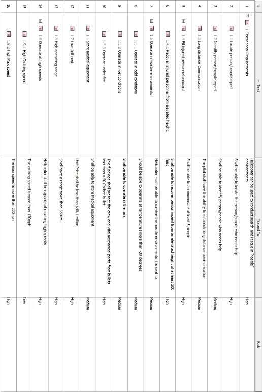
These requirements were then placed into a SysML Requirements table, which allows us to put the required information in a table format. This makes the requirements much more representable and allows us to add in information regarding the requirements, such as, high cruising speed: Shall be able to travel faster than 200mph. The others can be seen in figure 3. It is at this stage were the non-functional requirememnts are added, to ensure that all the requirements can be found in one place. Each requirement is then given a piority rating (under the colloum risk) according to the importance of the requirement. Pioritisation was decided off the combination of the customers needs and how much of an effect the requirement has to the overall operational requirements.

Following on from this, the key design features were decided and justified. This a critial section for systems engineers when they are deciding the likely trade-offs. The pioritisation and justifications are what influences the decisions on which trade-offs will be considered.
|
Type |
Requirement |
Key Design Feature |
Piority |
Justification |
|
Non-Functional |
1.4 Fit injured personnel onboard |
Shall be able to accommodate at least 8 people |
High |
The HH-60G Pave Hawk is the best helicopter for search and rescue at the moment, which can hold up to 12 people and the six crew members onboard. Taking into consideration this is when all people are healthy and not injured the stakeholders agreed that 8 injured people must be able to fit inside the helicopter. |
|
Non-Functional |
1.4.1 Recover injured personnel from elevated height |
Shall be able to recover person imperil from an elevated height of at least 200 feet |
High |
The stakeholders wanted the system to have the cabalility to extract injured personnel from an elevated hieght. |
|
Non-Functional |
1.5.1 Operate in cold conditions |
Should be able to operate at temperatures more than -30 degrees |
Medium |
The system must be able to operate in harsh weather conditions, which includes subzero tempreatures. The engines in the HH-60G Pave Hawk can operate efficiently in -30 degress [6]. As we are creating a system that should be able to rival the best S&R helicopters out there, we decided our engines should be able to operate under the same conditions as the HH-60G Pave Hawk. |
|
Non-Functional |
1.5.3 Operate under fire |
The fuselage shall protect the crew and vital mechanical parts from bullets less than a 50 Caliber bullet |
High |
As the stakeholder highlited the fact that this S&R Helicopter would be used in the military as well as natural desasters, it is essential for the system to be able to withstand small arms fire and automatic weapons. This would be anything less than a 50 caliber bullet. |
|
Non-Functional |
1.8 High operating range |
Shall have a range more than 650km |
High |
Currently the S&R helicopter that has the smallest range is the black hawk helicopters, with the range of 592km. The coustmer stated that they would like the helicopter to rival thoes that are the best in the market as well as keeping the cost down, we decided that having the minimum 100km more than the lowest range out there, will give our system the competitive edge it needs. |
|
Non-Functional |
1.9.1 High Cruising speed |
The cruising speed is more than 170mph |
Low |
Looking at the curising speed of the HH-60G Pave Hawk, which is at 184mph. This system needs to rival it as well as keeping the cost low. So the best way to do that is keep the cruising speed relatively close the to the Pave Hawk, but reducing it slightly to lower the costs. |
|
Non-Functional |
1.9.2 High Max speed |
The max speed is more than 200mph |
High |
Looking at the max speed of the HH-60G Pave Hawk, which is at 220mph [1]. This system needs to rival it as well as keeping the cost low. So the best way to do that is keep the max speed relatively close the to the Pave Hawk, but reducing it slightly to lower the costs. |
|
Non-Functional |
1.7 Low unit cost |
Unit Price shall be less than $40.1 Million |
High |
Analysing the market, the best helicopter (HH-60G Pave Hawk) has a unit cost of $40.1 Million. So keeping the price less than the Pave Hawk, will make it more appealing to the coustomers. |
Figure 4: Key Design Features Justification
2.5 Requirements Model (Relations)
From the requirements table in figure 3, a requirements model was created showing the relationships between each requirement. As you can see in figure 5, all the requirements can be seen mapped back to the operational requirement. This shows the relationships between each of the requirements and how they are vital for the system to achieve its operational requirement. In addition, this tool allows us to highlight the requirements that are derived from other requirements. For example, in figure 5, requirement 1.5 “Operate in hostile environments”, has three other requirements that are derived from it. 1.5.1 “Operate in cold conditions”, 1.5.2 “Operate in wet conditions” and 1.5.3 “Operate under fire. Something that should be noted is that these three requirements are not all functional requirements. Even though 1.5.1 is a functional requirement 1.5.1 and 1. 5.2 are both non-functional requirements.

3.1 SysML Block Definition Diagram (BDD)
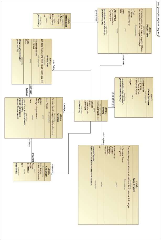
Block Definition Diagram is used to define the different types of physical units as well as intangible entities [7] [4] [5]. Furthermore, the BDD defines each blocks characteristic in terms of it structural and behavioral features [7]. The diagram can be used to plot the requirement constraints that have been identified previously in the report [4] [5]. Finally, the BDD allows the user to define the relationships between each block, for example the hierarchical relationships [7].
Figure 6 is the Block Definition Diagram for the S&R Helicopter System, which as seen, has eight main blocks: Fuselage, Power Plant, Rotor Blades, Battery, Hoist Cable, Visual Software, Radio system, Armament.
The Fuselage block is associated to two other blocks (which is represented with a straight line, that has no arrow at the end), Hoist Cable and Armament. The reason for this is because both the Armament and Hoist Cable is connected to the Fuselage. The reason for there not being a direct association line between these three is due to the fact that there is no signal flow between these subsystems. On the other hand, if we look at the Battery and the Fuselage there is a direct association line since the battery will power the lights and other electrical equipment inside the fuselage. In addition to the fuselage the battery also has a direct association line with the visual software, radio system, hoist cable and power plant. The reason for this is because all these subsystems need electrical power to work and carry out their operations.
Each block has specific operations that it needs to carry out, in order for the overall system to achieve its goal. Visual software must be allow the pilot to locate and identify the person/people imperil (see requirement 1.1 and 1.2), in order to do so it has to have the capabilities to see in the dark, which means the subsystem needs to generate night vision display. By looking at the rest of the blocks it is now easily identifiable, of their purpose in the overall system and how each subsystem aids the overall system in achieving the requirements.

3.2 SysML Internal Block Diagram
An Internal block diagram can be interpreted the complete opposite of the block definition diagram due to the reason that an IBD is a white box or internal view of a system block [4] [5]. The blocks in the BDD are represented in the IBD as parts. This just means that this diagram illustrates the flow properties between each subsystem.
Figure 7 is the IBD for the S&R helicopter system which can be traced back to the Block Definition Diagram in chapter 3.1. As you can see in figure 7, the power plant block has a port, which links to the ‘Fuel’ flow property. This illustrates how the fuel is supplied from a different part of the system (Fuel Tank) that is outside of our scope. After receiving electrical power from the battery, the power plant (engines) can then ignite the fuel which then generates power. This power is then transferred to the Rotor Blades, which is not only represented with an association line but the “Direction” label indicates where the energy flow is going. So, from the power plant the power is going out into the rotor blades, which is then transferred into torque. This torque then generates lift, allowing the helicopter to fly.
Moving onto another section of the diagram, the Fuselage has only one flow property, which is people. The reason for this is because the fuselage has one main purpose, which is to allow people to enter and exit the helicopter. Even though flow property is considered the flow of energy, in this case people are considered a flow of energy. The flow property “people” is then connected to the “torque” flow property of the hoist cable, as the torque energy lifts the people from the ground into the helicopter. Finally, if we continue analyzing the fuselage, you can see that the flow property is only linked to one other flow property, but there is still an association line between the fuselage and the armament. The reason for this is because we know that the armament in placed inside the fuselage so these two subsystems are connected, but as far as we know there is no flow of energy between them.
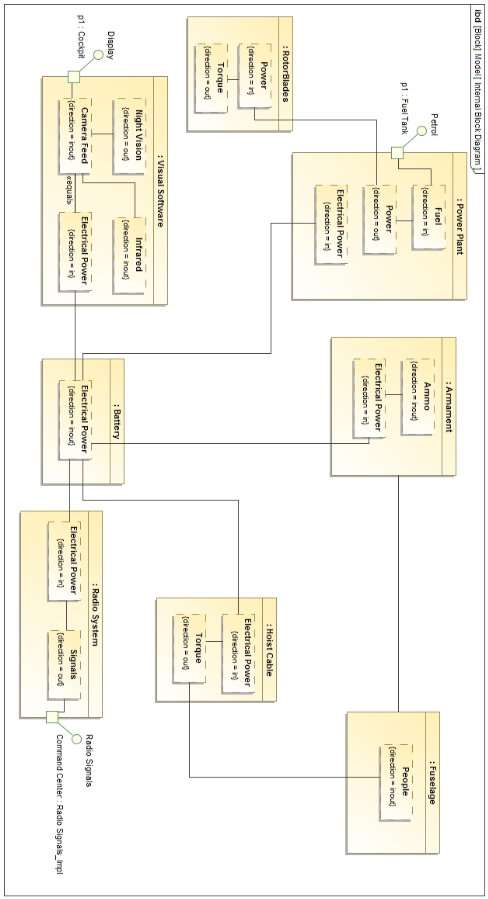
Figure 7: Internal Block Diagram
3.3 Association Matrix
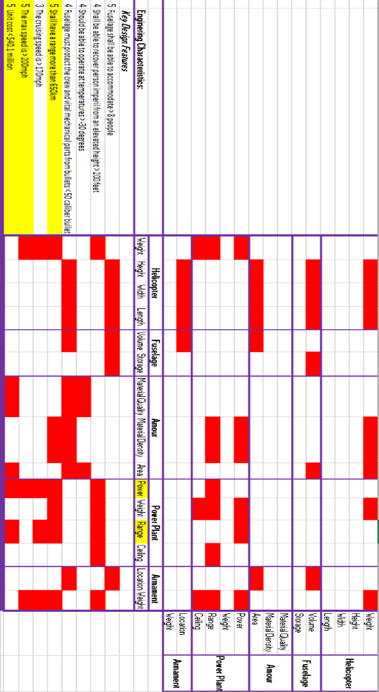
In this section of the report we will explore the key design features that was provided by the costumer [5]. These key features are the ones that influence the system requirements significantly. To illustrate this, the key features were matched with its corresponding engineering characteristics, which allowed us to figure out the strength of their connection [5]. Figuring out the strength of their connection lead on to us deciding what the tradeoffs were.
If we analyses figure 8, we can see that the engineering characteristics are categorized into five different sections:
- Helicopter
- Fuselage
- Amour
- Armament
- Power Plant
The Helicopter category represents the whole system, which allows us to illustrate the relevance of each engineering characteristic with the overall system [8] [5]. For instance, the volume of the fuselage is affected by the height, width and length of the helicopter as well as the other engineering characteristics from the other sections. Looking at the Power characteristic, we can see that it is affected by weight of the armament, range and weight of the power plant, the material density of the amour and the weight of the helicopter its self. This indicates that this particular engineering characteristic needs to be taken into careful consideration when designing the system. Similarly, the Range of the power plant is also affected by a majority of the other engineering characteristics.
Keeping these two engineering characteristics in mind, if we look into the key design features, we can see that Power and Range (of the Power Plant) affects quite a few of the key design features that are ranked at a priority of 5. Therefore, the tradeoffs we will be analyzing will be the ones highlighted in yellow.

3.4 Block Constraint Diagram
From the previous section of the report (3.3), the key design features that have been chosen are “Unit cost < $40.1 million", which links to requirement 1.7 and "shall have a range more than 650km", which links to requirement to 1.8. The Parametric diagram and the Block Constraint diagram is then utilized to determine the tradeoffs between the engineering characteristics [4].
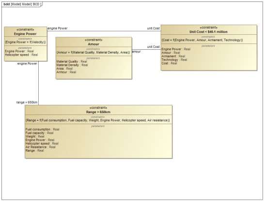 Figure 9, illustrates the Block constraint diagram created to determine the tradeoffs between the engineering characteristics. It does this by determining which engineering characteristic directly affect the key design features [5]. The blocks in figure 9 can be considered as functions, which is illustrated by the constraints subheading in the block. Using the, “Unit cost <$40.1 million" block as an example, we can see that the function is mathematically calculated with a combination of the variables; Engine power, Amour, Technology and Armament. Due to the fact that Engine power and Amour can be calculated with their own functions, they are included in the BCD to depict a more accurate illustration of the engineering characteristics compared to the key design features. Similarly, with the block "Range > 650km”, the function of this is mathematically calculated with the combination of the variables; Fuel consumption, Fuel capacity, Weight, Engine Power, Helicopter speed and Air resistance.

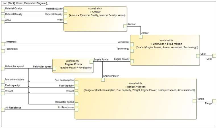
3.5 Parametric Diagram
Similarly, in a sequential viewpoint is used to help with the analysis of the tradeoffs. Figure 10 is a Parametric diagram which demonstrates the engineering characteristics that are used to calculate the range and unit cost functions [9] [4]. From the diagram and research, it became clear that if you increase the power of the engines the range of the S&R Helicopter systems starts to decrease. Looking at the function of the unit cost, you can see that “Engine Power” is included in the function, meaning that if you decrease the “Engine Power” the unit cost will reduce with it. This illustrates the tradeoffs of the engineering characteristic and key design features. Further detail in how to optimize the tradeoffs will be done in the next section.

Trade offs must be made to ensure that the system satisfies majority of the requirements that was stated at the beginning of this report. As stated in the previous section of this report (3.4), the parameters we will be focusing on when trying to optimise the tradeoffs are “Motor Power”, “Unit Cost <$40.1 million" and "Range > 650km”. To illustrate where the optimal point will be between the three tradeoffs, a graph was created with all three parameters.
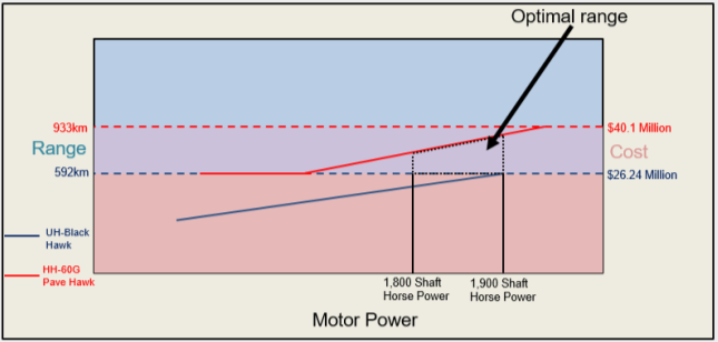

 The graph above indicates the area where the optimal tradeoff will be. This was calculated with the research information on the different engines that are used in the market and their outputs. You can see that two main competitors that were used, the UH-Black Hawk and the HH-60G Pave Hawk, are indicated with the red and blue lines. During the research, the motor power of each helicopter was looked up and compared to the range that they produced. After gathering enough data, a graph was created that would indicate the relationships between the findings. You can see that as the motor power increases the range of the engines start to increase after a certain point. In doing so the cost of the system starts to increase dramatically too.
The report has explored how the current systems that are in the market, such as the HH-60G Pave Hawk and the UH-Black Hawk. Which allowed us to get a better understanding of what type of competitors the S&R Helicopter will face. The next stage was to define the stakeholder and user requirements, which was achieved in the methods section. Creating the requirements table allowed us to verify and validate that we created the right system and the system that the customers asked for. To create the requirements table and other diagrams such as the BDD, IBD etc., SysML modeling languages were used, which allowed us to analys the system designed.
Finally, the report comes to the following recommendations. Since the requirement was to keep cost as low but keeping the S&R Helicopter in the competitive race in the market, the maximum cost for the S&R Helicopter was reduced just below the Pave Hawk, at $38 Million. Reducing the cost meant that the motor power was also reduced, which in return reduced the range. The motor power didn’t suffer that much on reduction but the range drop was more significant. Reducing the motor power by just 100 Shaft Horse Power meant that the range dropped from 900km to 730km. On the other hand, this is still acceptable as the requirements stated that the range had to be greater than 650km, which it is and with the shaft horse power being at 1,800 shaft horse power the engine can still reach maximum speeds above 200mph.
|
[1] |
“HH-60G Pave Hawk,” , . [Online]. Available: http://www.af.mil/AboutUs/FactSheets/Display/tabid/224/Article/104508/hh-60g-pave-hawk.aspx. [Accessed 15 3 2017]. |
|
[2] |
S. E. |. “.-6. P. H. {{cite journal |last= Young |first= Susan H.H. and S. H. S. E. Young, “2008 USAF Almanac,” Air Force Magazine, vol. 91, no. 5, p. 155-156, . |
|
[3] |
Airforce-technology Editors, Kable Intelligence Limited, 2017. [Online]. Available: http://www.airforce-technology.com/projects/sikorsky-hh-60g-pave-hawk-combat-search-rescue-helicopter/. [Accessed 8th March 2017]. |
|
[4] |
O. D. A. &. C. Guillaume FINANCE, “SysML Modelling Language explained,” 7 October 2010. [Online]. Available: http://www.omgsysml.org/SysML_Modelling_Language_explained-finance.pdf. |
|
[5] |
D. N. M. C. Dickerson, “Architecture and principles of systems engineering, CRC Press, 2010. |
|
[6] |
A. O. Hyg, “Cold Exposure During Helicopter Rescue Operations in the Western Alps,” 01 January 2003. [Online]. Available: https://academic.oup.com/annweh/article/47/1/7/131313/Cold-Exposure-During-Helicopter-Rescue-Operations. |
|
[7] |
T. Editors, “Block Definition Diagram (bdd),” [Online]. Available: https://www.threesl.com/cradle/help/System%20Modelling/other/bdd.htm. [Accessed 5th March 2017]. |
|
[8] |
P. H. I. A. P. D. J. Hatley, Process for system architecture and, 2000: Dorset House Pub. |
|
[9] |
D. W. e. al, Systems Engineering Handbook: A Guide for System Life cycle processes and activites. |
|
[10] |
Wikiwand Editors, “General Electric T700,” [Online]. Available: http://www.wikiwand.com/en/General_Electric_T700. [Acces Cite This WorkTo export a reference to this article please select a referencing stye below:
Reference Copied to Clipboard.
Reference Copied to Clipboard.
Reference Copied to Clipboard.
Reference Copied to Clipboard.
Reference Copied to Clipboard.
Reference Copied to Clipboard.
Reference Copied to Clipboard.
Related ServicesView allDMCA / Removal RequestIf you are the original writer of this essay and no longer wish to have your work published on UKEssays.com then please click the following link to email our support team: Request essay removalRelated Services Our academic writing and marking services can help you! Freelance Writing Jobs Looking for a flexible role? Study Resources Free resources to assist you with your university studies! |


