Future Railway Energy Supply and Motive Power Systems
| ✅ Paper Type: Free Essay | ✅ Subject: Engineering |
| ✅ Wordcount: 3087 words | ✅ Published: 23 Sep 2019 |
Future Railway Energy Supply and Motive Power Systems
TABLE OF CONTENTS
1.1 Railway Industry need for De-carbonisation
1.2 Hydrogen – Tomorrow’s Fuel
2.1 Class 170 – Performance Calculation
2.1.1 Traction Performance – With Full Payload (Crush Load)
2.1.2 Traction Performance – Without Full Payload
3 Class 170 – Hydrogen Powered
3.2 Hydrogen Power Plant & Weight
3.3 Hydrogen Powered Replaced System
LIST OF TABLES
Table 1 Train/Power Module Characteristics [7] [8] [9] [10]
Table 2 Traction Performance at Crush Load of Class 170 – DMU
Table 3 Traction Performance at Tare Mass of Class 170 – DMU
Table 4 Hydrogen Pack Replaced Effective Mass
Table 5 Traction Performance – Hydrogen Powered System Class 170
Table 6 Braking Performance – Hydrogen Powered System Class 170 [14]
Table 7 Predicted Carbon Emissions
Table 8 Class 170 Performance Summary
GLOSSARY
CSM RA – Common Safety Method Risk Assessment
CDP – Capability Development Plan
RD&T – Research, Development and Technology
CP6 – Control Period 6
BCRRE – Birmingham Centre for Railway Research and Education
CCS – Control Command and Signalling
TOCs – Train Operating Company
DMU – Diesel Multiple Units
GTR – Govia Thameslink Railway
DMCL – Driving Motor Composite with Lavatory
MS – Motor Standard
PMSM – Permanent Magnet Synchronous Motor
1. Introduction
In 2012, a Rail Technical Strategy’s CDP was published. It was a joint consultation between rail experts, which identified 12 key capabilities that railway needed to develop on to meet the increasing passenger capacity demand and focusing on sustainability. This was a challenge for shifting the culture of rail sector which invested minimal on RD&T to investing in RD&T which focuses on improving productivity and performance of the rail transport. Industry like Network Rail has pledged to exploit the value of approx. £1.3Bn per annum toward the end of CP6 in conjunction with Shift2Rail programme [1].
A hierarchy has been setup and major technical develop programmes have been identified as follows [1] –
- CCS
- Energy
- Infrastructure
- Rolling Stock Energy
- Information
- Customer Experience
These programmes are designed for delivering key outcomes as follows [1] –
- Decarbonisation – Halve Carbon: Optimal Energy Use
- Double Capacity
- Improving Customer Experience
- Halving Cost
1.1 Railway Industry need for De-carbonisation
U.K government plans to electrify the rail network to cut emissions, this is costly approach and Britain has been heavily reliant on coal-based electricity production. As reported by the guardian newspapers, Diesel trains are still more responsible for CO2 emissions than electric trains [2] . Network Rail owns 20,000 miles of track out of which only 40% is currently electrified. Some prominent electrification projects are currently underway like GWEP, EGIP and Gospel Oak to Barking, which are successfully being executed but involves high cost as it relies on electrification infrastructure [3]. The transport including trains and cars account for 26% of U.K CO2 emissions [4]. As mentioned above, U.K government has ambitious by 2040 to reduce these hydrocarbon emissions significantly by introduction of new technologies like hybrid and/or alternative fuels [4]. It is also not cost-effective in some cases to electrify railway for which discontinuous electrification, intelligent energy source and alternative fuels are significantly researched and invested. For all the above-mentioned reasons, railway industry is no less.
For which Network Rail along with joint consortium of railway experts have identified the 12 RD&T key capabilities and approx. £228 million has been pledged towards optimal energy usage like intelligent energy storage and distribution technologies for delivering the decarbonisation agenda. The optimum energy use can be further broken into aspects like Smart Grid Technologies, Battery/Dual Power Systems, Non-Diesel Alternatives and Transferring energy [1].
Optimal Energy Usage – The major milestone to achieve here is decarbonisation by introduction of technologies like hybrid operation. Hybrid trains enables for discontinuous electrification on non-electrified rail tracks and uses electrical traction to run on network without overhead electrification [1].
Thus, the focus is to significantly reduce railway’s carbon footprint by investing and investigating into renewable energy systems like hydrogen and biofuels etc. Likewise, BCRRE has demonstrated via their ‘Hydrogen Pioneer’ – U. K’s first hydrogen powered train for an IMechE Railway Challenge [2].
1.2 Hydrogen – Tomorrow’s Fuel
The decarbonisation agenda is plausibility with help of the first element of the periodic table, i.e. hydrogen with atomic number 1. Hydrogen is known to be generated by using techniques like electrolysis or chemical processes [6]. It is one of the purest form of energy as it is combustible at high concentration and generates electricity and heat at the expense of ‘pure water H2O’ as exhaust. A fuel cell is highly considered for powering the vehicles as it produces greener electricity. Some of the European countries have already established that hydrogen operated trains are not only cheaper as compared to diesel and electric but greener as well [6]. From an operation prospective, hydrogen train can be utilised in no different ways as compared diesel like hydrogen shares similar refuelling patterns with diesel. From traction prospective, hydrogen trains can achieve similar travel ranges, speed and hours of operation when compared diesel [6]. This assignment focuses on one of most common modes of hydrogen production, i.e. SMR – Steam Methane Reforming [6].
1.3 Aims and Objectives
Aim
To develop concept design for powering the train of the next generation for TOCs in the U.K. To demonstrate the agenda of decarbonisation and application of CSM-RA for any improvement to the existing rolling stock.
Objectives
- To show overall train performance specification which includes calculations of train performance.
- To demonstrate a safety case by carrying out CSM-RA for the overall changes to the train performance adhering to the agenda of decarbonisation.
1.4 Methodology
In this assignment DMU is chosen as a benchmark train. The following performance calculations is shown for the DMU –
- Traction Performance –With Full Payload (Crush Load)
- Traction Performance – Without Payload
Then a prospective of replacing the diesel as primary source with hydrogen for meet the decarbonisation agenda and the following performance calculation is shown for hydrogen-hybrid train –
- Traction Performance –With Full Payload (Crush Load)
- Traction Performance – Without Payload
- Braking Performance – With Full Payload
- Energy Consumption.
A comparative analysis between DMU and hydrogen hybrid train. A CSM-RA for introduction of hydrogen fuel technology on the chosen vehicle as shown in section 2.
2 Vehicle Type
The British DMU Class 170 Turbostar is the chosen vehicle type built by Bombardier. This DMU entered service in 2001 and has been used by some busiest TOCs like Abellio ScotRail and GTR [7]. For this assignment the following train characteristics were used for train performance calculations –
Table 1 Train/Power Module Characteristics [7] [8] [9] [10]
|
Train/Power Module Characteristic |
|
|
Axle Per Car |
4 |
|
Vehicle Width (m) |
2.69 |
|
Vehicle Height (m) |
3.77 |
|
Tare Mass (tonne) |
168.50 |
|
Payload (tonne) |
21.51 |
|
Total Mass (tonne) |
190.01 |
|
Maximum Acceleration (m/s2) |
0.50 |
|
Maximum Speed (mph) |
100 |
|
Diesel Tank Capacity (L) |
1500 |
|
Energy Available in Diesel Tank (kWh) |
14910 |
|
Body Structure |
Welded Aluminium |
|
Power Unit Type |
1x MTU 6R 183TD 13H |
|
Unit formation (4 Car) |
DMCL-MS-MS-DMCL |
|
Total Seating Capacity |
262 |
|
Traction Type |
Diesel |
|
Fleet Configuration Car Units |
2 x 4 |
|
Motor RPM (revs/s) |
1900 |
The Class 170 has a basic design and is a preferred regional commuter. The body structure is made up of welded aluminium. Class 170 has subclasses from 170/1 to 170/6. The total fleet size currently held by Eversholt Rail Group is 27 and chosen configuration for this paper is 4 car unit with total capacity of 262 passengers [7].
2.1 Class 170 – Performance Calculation
Using the train characteristic as mentioned above, performance of the Class 170 was calculation using with/without payload of the train.
How was payload of the train calculated?
As the 2x 4 car configuration was used, the total seating capacity was 262. Assuming the train was full capacity with average person weight as 70 Kg and each carrying average luggage of 15 kg each, the total was 85 kg per seat. Hence, the payload was –
2.1.1 Traction Performance – With Full Payload (Crush Load)
The Class 170 has 2 DMU, each containing a diesel engine each as represented by train configuration of DMCL-MS-MS-DMCL [9]. At full payload, i.e. the crush load, the following detailed performance has been calculated –
Table 2 Traction Performance at Crush Load of Class 170 – DMU
|
Parameters |
Values |
References |
|
Number of Cars |
4 |
2 x 4 Car Units – Formation |
|
Tare Mass (tonnes) |
168.5 |
|
|
Rotary Allowance |
0.12 |
12% as body of train is Welded Aluminium |
|
Payload (tonnes) |
22.27 |
|
|
Effective Mass (tonnes) |
210.99 |
Me = Tare Mass (1 + Rotary Allowance) +Payload |
|
Top Speed (mph) |
100 |
|
|
Speed of Train (m/s) |
44.70 |
|
|
Number of Axles per Car |
4 |
|
|
Acceleration of Train (m/s2) |
0.5 |
|
|
Wheel Diameter (m) |
0.9 |
[11] |
|
Davis Equation R = A + Bv +Cv2 |
||
|
A |
4219.80 |
20 N/tonne |
|
Bv |
2.68 |
B – 0.06 [10] |
|
Cv2 |
11.99 |
C – 0.0067 [10] |
|
Train Resistance (kN) |
4.23 |
|
|
Traction Force (T.F) (kN) |
105.50 |
(F = Me x a) |
|
T.Fmax (kN) |
109.73 |
T.F + Train Resistance |
|
Pmax (MW) |
2.45 |
T.Fmax x V/2 |
|
Available Adhesion (µ) |
0.12 |
(µ > 0.12 UK Passenger Train) |
|
T.E (kN) |
248.38 |
µ x me x g & g = 9.81 m/s2 |
|
Required Traction Force (kN) % |
44 |
(T.Fmax/T.E) |
|
Total Number of Axles |
16 |
|
|
Motored Axles |
7 |
16 x 44% |
|
Power of Each Motored Axle (kW) |
347 |
Pmax/7 |
|
Motor RPM (revs/s) |
1900 |
|
|
Motor Angular Velocity (ɷm – rad/s) |
199 |
|
|
Wheel Angular Velocity (ɷw – rad/s) |
99 |
ɷm/ɷw |
|
Gear Box Ratio |
2 |
|
|
Motor Torque (kNm) |
3.49 |
|
|
Wheel Torque (kNm) |
6.99 |
|
|
Auxillary Power (kW) |
30 |
This an assumption |
|
Maximum Engine Output (kW) |
377 |
347 + 30 |
2.1.2 Traction Performance – Without Full Payload
At tare mass, i.e. the empty load, using the same methodology and train characteristics as shown in table 2, the key performance details are as mentioned in table 3 below –
Table 3 Traction Performance at Tare Mass of Class 170 – DMU
|
Parameters |
Values |
References |
|
Tare Mass (tonnes) |
168.5 |
|
|
Rotary Allowance |
0.12 |
12% as body of train is Welded Aluminium |
|
Payload (tonnes) |
0 |
|
|
Effective Mass (tonnes) |
188.72 |
Me = Tare Mass (1 + Rotary Allowance) |
|
Train Resistance (kN) |
3.79 |
|
|
Traction Force (T.F) (kN) |
94.36 |
F = Me x a |
|
T.Fmax (kN) |
98.15 |
T.F + Train Resistance |
|
Pmax (MW) |
2.19 |
T.Fmax x V/2 |
|
Available Adhesion (µ) |
0.12 |
µ > 0.12 UK Passenger Train |
|
T.E (kN) |
222.16 |
µ x me x g & g = 9.81 m/s2 |
|
Required Traction Force (kN) % |
44 |
T.Fmax/T.E |
|
Motored Axles |
7 |
16 x 44% |
|
Power of Each Motored Axle (kW) |
310 |
Pmax/7 |
|
Gear Box Ratio |
2 |
|
|
Motor Torque (kNm) |
3.12 |
|
|
Wheel Torque (kNm) |
6.25 |
|
|
Auxillary Power (kW) |
30 |
This an assumption |
|
Maximum Engine Output (kW) |
340 |
347 + 30 |
3 Class 170 – Hydrogen Powered
For meeting the requirement of decarbonisation, a cleaner and greener alternative fuel, i.e. hydrogen as discussed in section 1.2 is considered for this assignment. The drive system of the concept design is as shown in figure 1 below –
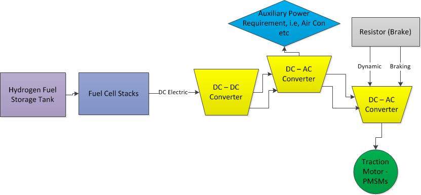
Figure 1 Class 170 – Hydrogen Powered System [10]
3.1 Traction Motor – PMSMs
From figure 1, the chosen traction motor for the conceptual design is a PMSMs. A hybrid of induction and brushless DC motor, PMSMs are emerging motor type for traction designer it has great advantage of high power density as compared to induction motors at a similar rating. They are light weight and have smaller diameters, as light weight helps for saving energy by lowering the effective mass. Also, the PMSMs enables dynamic braking at lower speeds which will be beneficial for regional commuting purpose of the Class 170. [12]
3.2 Hydrogen Power Plant & Weight
From table 2, the required power is 377 kW for DMU. 7 Hydrogenic’s Celerity 60 kW will be used delivering a combined power of 420 kW. This has expected lifetime of 10000+ hours and has a combined mass and volume of 1.925 t and 2.03 m3 [13]. However, the required power will reduce when replaced by hydrogen system, saving energy and thus, the carbon emissions.
2x 4 car configuration has 2 DMUs. This has to be replaced with hydrogen tank and fuel stack cells stack as shown in figure 1 above. 2x DMU will weigh approximately 8.4 tonnes [13]. Replacing this with 14 Hydrogenic’s Celerity weighs 3.85 t.
Therefore, new effective mass (Me) –
Table 4 Hydrogen Pack Replaced Effective Mass
|
Effective Mass (t) |
210.99 |
from Table 2 |
|
2x Diesel Engine System (t) |
8.4 |
[13] |
|
New Effective Mass (t) |
202.59 |
|
|
% Weight Decrease |
4% |
3.3 Hydrogen Powered Replaced System
Upon replacing the DMU s with hydrogen system, 4% weight is reduced. However, the required power is reduced when replaced by hydrogen system, saving energy and thus, the carbon emissions.
Table 5 Traction Performance – Hydrogen Powered System Class 170
|
Parameters |
Values |
References |
|
Tare Mass (tonnes) |
168.5 |
|
|
Payload (tonnes) |
22.27 |
|
|
2x DMUs (tonnes) |
8.4 |
|
|
Effective Mass (tonnes) |
202.59 |
Me = Tare Mass (1 + Rotary Allowance)+Payload |
|
Pmax (MW) |
2.35 |
T.Fmax x V/2 – Power Required to Move the Train |
|
Motored Axles |
7 |
16 x 44% |
|
Power of Each Motored Axle (kW) |
333 |
Pmax/7 |
|
Maximum Hydrogen Output (kW) |
363 |
Auxillary Power – 30 kW |
3.4 Braking Performance
As the DMU utilised Air Brakes, when replacing this system with hydrogen dynamic braking will be utilised in form of regenerative braking. The calculations shown below in table 6 show the braking performance of Class 170 hydrogen powered.
Table 6 Braking Performance – Hydrogen Powered System Class 170 [14]
|
Parameters |
Values |
References |
|
Train Type |
Class 170 |
|
|
Maximum Speed (mph) |
100 |
|
|
Maximum Speed (kph) |
160.9 |
|
|
Maximum Speed (m/s) |
44.70 |
|
|
Tare Load (t) |
168.5 |
|
|
Max Load mass mml (t) |
182.4 |
|
|
Gradient |
1:40 |
Assumption |
|
Stopping Distance Target (m) |
1701 |
[14] |
|
10% margin for Stopping Distance Target (m) |
1530.9 |
|
|
Number of Units |
4 |
|
|
Brake Application Time (s) |
2.5 |
b/w 2.0 to 3.0 s |
|
Brake Response Distance sr (m) |
111.76 |
|
|
Braking Distance sb (m) |
1475.02 |
|
|
Effective Mass me (t) |
195.85 |
0.08 – Motored, (me = (mml + (mt x 0.08)) |
|
Deceleration ai (m/s2) |
0.68 |
|
|
Deceleration Force Fd (kN) |
132.67 |
Fd = me x ai |
|
2/3 x Max Speed (kph) |
107.27 |
|
|
rm = Mech/Track Resistance (N/tonne) |
4508.19 |
BR Brake Performance Table |
|
rw = Air Resistance (N/Vehicle) |
1170.42 |
|
|
ro = Head and Tail Resistance (N/Train) |
747.54 |
|
|
Vehicle Resistance Fr (kN) |
6.43 |
|
|
Brake Force Required Fb (kN) |
126.24 |
(Fb = Fd – Fr) |
|
Braking Power Pb (mW) |
5.64 |
|
|
Pb per wheel (kW) |
705.41 |
|
|
Emergency Brake (kN) |
164.11 |
30% x Fb |
|
Emergency Deceleration Force (kN) |
170.54 |
(Fd = Fb + Fr) |
|
Emergency instant deceleration ai (m/s2) |
0.87 |
|
|
Emergency braking distance sb (m) |
1147.69 |
|
|
Emergency Stopping Distance (ss = sb + sr) (m) |
1259.22 |
1259.08 > 1053 [14] |
|
Emergency braking power (mW) |
7.62 |
|
|
Gradient Brake Performance (kN) |
44.73 |
4 Carbon Emissions and Performance
Upon referring to various sources, an assumed annual mileage for Class 170 2x 4 configuration on the U.K network is 700,000 miles [15]. For diesel rail journeys the CO2 emissions is 0.0602 kg CO2/km. As per section 3.4 of [16], CO2 emission of fully hydrogen powered train is approx. 9% of a diesel train, i.e. 0.00542 kg CO2/km [16]. The carbon emissions are analysed for fleet of Class 170 for diesel and hydrogen fuels as shown in table 7 below –
Table 7 Predicted Carbon Emissions
|
Vehicle Type |
Source of Energy |
Annual Mileage (km) |
kg CO2/km – Fuel Type |
CO2 Emission – Kg |
|
Class 170 |
Diesel |
1183000 |
0.0602 |
71216.6 |
|
Class 170 |
Hydrogen |
1183000 |
0.005418 |
6409.5 |
|
Decarbonised Percentage |
91% |
|||
From table 7, hydrogen powered Class 170 decreases carbon footprint 91%. The hydrogen powered system generates electricity with exhaust as pure water and heat.
4.1 Performance Summary
Class 170 is analysed with DMU and Hydrogen powered to address the agenda of decarbonisation and the following performance summary is derived based on the analysis –
Table 8 Class 170 Performance Summary
|
Class 170 |
Diesel |
Hydrogen |
|
Available Adhesion (µ) |
0.12 |
0.12 |
|
Train Resistance (kN) |
4.23 |
4.07 |
|
Acceleration (m/s2) |
0.50 |
|
|
Deceleration (m/s2) |
0.68 |
|
|
Top Speed (mph) |
100.00 |
100.00 |
|
Power at wheels for Crush Load (kW) |
347.00 |
333.00 |
|
Power at wheels for No Pay Load (kW) |
310.00 |
296.00 |
|
Emergency Brake Distance (m) |
1259.22 |
|
|
Brake Performance at Gradient (kN) |
47.00 |
44.37 |
|
Type of Traction Motors |
Gear Box |
PMSMs |
|
Energy Consumption per wheel (mW) |
2.45 |
2.35 |
|
Carbon Emissions (kg) |
71216.6 |
6409.5 |
5 CSM-RA
Railway being a safety critical business, it is a mandated requirement to carry out risk assessment evaluation for any changes to rail infrastructure or rolling stock. Using a generic Network Rail’s CSM-RA form, a brief RA is carried out for the hydrogen powered Class 170 train –
|
COMPONENT OF TASK |
HAZARDS |
CONSEQUENCE |
EXISTING |
L |
S |
R |
ADDITIONAL |
Residual Risk |
|||||
|
CONTROLS |
CONTROLS |
L |
S |
RR |
|||||||||
|
Train Rooftop Storage – Hydrogen System |
Electrocution |
Burns or Death |
Utilising a small surface area of the train rooftop for storage of hydrogen system |
3 |
5 |
15 |
Insulation of the rooftop |
1 |
5 |
5 |
|||
|
Increased Braking force at gradient (1:40) |
Falls and uncomfortable braking force |
Head and/or body injury |
Reducing weight of train by using alternative fuel options than Diesel |
4 |
3 |
12 |
Using PMSM motors and hydrogen fuel cell stacks |
1 |
3 |
3 |
|||
|
Destruction of PMSM [17] |
Electrocution due to short circuit |
Burns or Death |
Demagnetisation |
2 |
5 |
10 |
Insulation around the PMSM storge on the train |
1 |
5 |
5 |
|||
|
GENERAL SUMMARY |
|||||||||||||
|
|
|||||||||||||
|
The task is high risk and presents high risks as the works will be on rolling stock of Class 170 |
|||||||||||||
|
CONDUCTED BY: |
Mohammad Ahmad |
ACCEPTED BY: |
|||||||||||
|
TITLE: |
E&P Engineer (HS) |
TITLE: |
|||||||||||
6 Conclusion
The Class 170 Turbostar train characteristics were used to calculate the overall diesel and hydrogen performance. From table 7, it was eloquent that Hydrogen powered train does help significantly towards the agenda of decarbonisation. Hydrogen powered not only becomes greener but has decreased weight and lower energy consumptions as compared to Diesel Powered Class 170 train.
REFERENCES
|
[1] |
N. R. -. C. b. G. Hopkins, “Rail Technical Strategy – Capability Development Plan,” RSSB (Link – https://www.rssb.co.uk/rts/Documents/2017-01-27-rail-technical-strategy-capability-delivery-plan-brochure.pdf), Milton Keynes, 27/01/2017. |
|
[2] |
G. NewsPaper, “Emissions by transport type,” Guardian NewsPaper, London, 2 September 2009. |
|
[3] |
N. Rail, “Who are we,” Network Rail, 2018. [Online]. Available: https://www.networkrail.co.uk/who-we-are/. |
|
[4] |
J. Gabbatiss, “Transport becomes most polluting UK sector as greenhouse gas emissions drop overall,” Independent Newspaper, 6 February 2018. [Online]. Available: https://www.independent.co.uk/environment/air-pollution-uk-transport-most-polluting-sector-greenhouse-gas-emissions-drop-carbon-dioxide-a8196866.html. |
|
[5] |
B. Staff, “Development and design of a narrow-gauge hydrogen-hyrbid locomotive,” Development and design of a narrow-gauge hydrogen-hyrbid locomotive, no. 25 March 2014, pp. 182 – 192, 6 November 2013. |
|
[6] |
G. N. K. G. G.D. Marin 1, “University of Ontario Institute of Technology, Faculty of Engineering and Applied Sciences, 2000 Simcoe Street North, Oshawa, Ontario,,” Rail transportation by hydrogen vs. electrification e Case study for Ontario, Canada, II: Energy supply and, p. 11, 2010. |
|
[7] |
E. U. R. Group, “CLASS 170 AND 171,” Bombardier, [Online]. Available: https://eversholtrail.co.uk/fleet/class-170-and-171/. |
|
[8] |
C. J. Marsden, Traction Recognition book, London, 2016. |
|
[9] |
A. V. Railway, “BR CLASS 107 DMU,” [Online]. Available: https://www.avonvalleyrailway.org/about-us/locomotives-rolling-stock/br-class-107-dmu/. |
|
[10] |
S. H. ,. R. E. Tajud Din, “University of Birmingham,” Energy consumption and carbon dioxide emissions analysis for a concept design of a hydrogen hybrid railway vehicle, no. DOI: 10.1049/iet-est.2017.0049, p. 14, 2018. |
|
[11] |
T. B. S. Institution, “BS 5892-7:2014,” Railway rolling stock materials, p. 62, 2015. |
|
[12] |
F. S. a. T. S. S Hillmansen, “The rise of permanent magnet traction motor,” The rise of permanent magnet traction motor, no. 1, p. 32, 2011. |
|
[13] |
Hydrogenics, “HyPM-HD Power Modules,” HyPM-HD Power Modules, p. 6, 2018. |
|
[14] |
S. P. Rail, “A world of Soluations,” A world of Soluations – Sales Program Rail, pp. 7-8, 2017. |
|
[15] |
RSSB, “Braking System Requirements and Performance for Multiple Units,” GM/RT2044, no. 4, p. 21, 2001. |
|
[16] |
Go-Ahead, “Moving People – Annnal Report and Accounts,” Go-Ahead, London, 2014. |
|
[17] |
L. M.-M. Z. P. Sabrina Chan, Analysis of GHG Emissions for City Passenger Trains: Is Electricity an Obvious Option for Montreal Commuter Trains?, no. 1, p. 4, 2013. |
Cite This Work
To export a reference to this article please select a referencing stye below:
Related Services
View all


DMCA / Removal Request
If you are the original writer of this essay and no longer wish to have your work published on UKEssays.com then please click the following link to email our support team:
Request essay removal