Permanent Magnet Synchronous Motor
| ✅ Paper Type: Free Essay | ✅ Subject: Mechanics |
| ✅ Wordcount: 4194 words | ✅ Published: 18 May 2020 |
Permanent Magnet Synchronous Motor
Efficiency plays an important role in increasing the productivity in industries. As a result, most of the companies now have become automated. Motors with drives plays an important role in make these aspects a reality. In most of the factories, Induction motors and Direct current (DC) motors accompanied with drives, are used to fulfil their requirements. But with the development of the magnetic capabilities in Permanent Magnets, now the focus has been given to Permanent Magnet Synchronous Motor (PMSM)s with drives. PMSM has proven effectivity in increasing the efficiency, high torque (Krishnan R. , 1987) and power output per unit volume, higher magnetic flux density in the air gap, simple construction and easy maintenance.
In early of 19th century with the invention of the magnetic laws, different types of motors have been developed. Most commonly used motor was Induction motor and DC motors. Operation principle of these motors can be explained with the above invented magnetic laws. Considering the pros and cons of each motor type, researchers performed developments. By the end of 1960s design of the traditional induction motors were combined with Permanent Magnet(PM)s so as to improve its capabilities. Providing maximum power density was one of the main aspects. Cahill and Adkins developed the mathematical model for the construction of PM on the rotor of the motor (Cahill & Adkins, 1962) which is based on 2 axis theory. Moreover, as the price of the earth magnets are becoming low and with the improvements in the field of semiconductors, control of permanent magnet motors become easier and cost effective. So that it can be operated over a large speed range while maintaining a good efficiency and power factor.
1.1 PM Materials
When an external magnetic field is applied, different materials shows different characteristics depending on electron structure of the material. Thus depending on the behaviour of the material they are classified into Paramagnet, Diamagnet and Ferromagnet. The properties are as follows:
| Diamagnet | Paramagnet | Ferromagnetic |
Eg: Copper, Silver. Gold |
Eg: Magnesium, Lithium, Tantalium |
Eg: Iron, Cobalt, Nickel (Krishnan R. , 2017) |
Due to the properties inherent in ferromagnets, they are used as the magnetic material in PM machines. The magnetic properties could be studied by using its hysteresis curve (The graph between the induced magnetic flux density(B) and Magnetizing force (H)). The basic magnetic parameters that are important in PM applications are remanence (Flux density corresponding to the zero magnetic field intensity), coercivity (Value of demagnetizing field necessary to bring the magnetic flux density to zero) and maximum energy product (Rahaman & Slemon, 1985). In order to be a PM, materials should possess with higher retentivity and a higher coercivity. The basis for the evaluation of the PM is based on the second quadrant of the B-H loop which is known as the demagnetizing curve (Gieras, 2010) .
PM used for electric motors were basically of three types. Namely Alnicos (Al, Ni, Co, Fe), Ceramics (ferrites) and rare earth materials.
- Alnico: Has high remanence and low temperature coefficients. Therefore, allow a high air gap flux density at high magnet temperature. But lacks with the high coercivity.
- Ferrites: Has a high coercivity than Alnico but has a lower remanence. Also has a high temperature coefficient. Advantages of using ferrites are economical and high electrical resistance, which stops from creating eddy current in the PM core (Petrov & Pyrhonen, 2013).
Eg- Strontium ferrite, Barium ferrite
- Rare Earth Materials: Has both high remanence and coercivity, but with a lower temperature coefficient.
Eg – Samarium Cobalt (SmCo), Neodymium Iron Boron (NdFeB)
In the beginning on the development of the PM machines only Alnico and Ferrites were used but with the development of the rare earth PMs, alternate options were provided for PM machines depending on its application (Rahaman & Slemon, 1985). As shown in Figure 1 Ferrite has the lowest coercivity and retentivity in the given condition. Ferrites are low cost. But due to the low remanence it occupies a big rotor space. Even though samarium cobalt has increased performance compared to ferrite, use of it is limited by the cost. With the developments of NdFeB in 1980s, it provided the merits of both ferrite and Samarium cobalt with a low cost. Furthermore, higher flux density could be produced with relatively small magnet volumes. Provided with the above-mentioned advantages, NdFeB was frequently used in designing PMSMs neglecting the limitations it has with low temperature limit (Petrov & Pyrhonen, 2013) and vulnerability to the corrosions.

Figure 1-Characteristic curve for different Permanent Magnet Materials at a temperature of 20 degrees. (Gieras, 2010)
Introduction of PM to the electrical machines which replace traditional rotor and stator structure are due to large number of reasons, some of them are:
- Field is provided by PMs. Thus, no excitation (Cahill & Adkins, 1962) loss is incurred creating a higher efficiency.
- Ease of maintenance
- Higher torque and power output per unit volume than machines with excitation
- Higher flux density in the air gap compared with machines which are excited electromagnetically
- Reduced cost
- Removal of slip rings (Gumaste & Slemon, 1981) in DC motors
…………………………………………………………………………………………………………………………………………………………….
1.2 PM Motors
PM electric machines can basically be categorised into two groups as Permanent Magnet Direct Current (PMDC) and Permanent Magnet Alternating Current (PMAC) machines. PMDC machines are similar to conventional DC motors except for the fact that PM replace the use of field winding.
PMAC machines are synchronous machines where magnets in the rotor generate the required field. Absence of commutator and brushes unlike in PMDC or conventional DC motors provide these motors higher performance. In order to produce the torque required PMAC machines should be excited with a current waveform. Depending on the type of the waveform PMAC machines are categorised as follows.

  PMAC Machines PMAC Machines |
|
| Trapezoidal type (BLDCM) | Sinusoidal type – Permanent Magnet Synchronous Machine (PMSM) |
Mainly divided in to two depending on the excited waveform given to the stator:
- PMDC – Excited using a trapezoidal waveform Produce a trapezoidal back emf in three phases which are 120 degrees from each other. Stator windings are concentrated into narrow phase pole
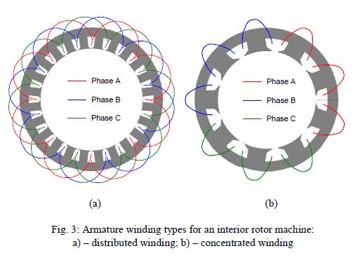
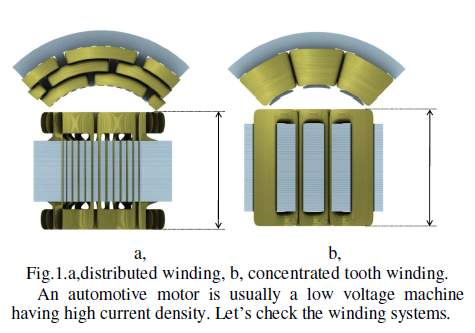
- PMSM (AC) – Excited using an AC waveform. Produce a sinusoidal back emf in three phases which are 120 degrees apart from each other. (Since the performance is close to conventional synchronous machines, known as PMSMs). Sinusoidal flux density distribution can be obtained by a balanced three phase current vectors provided to the stator (Jahns, Kliman, & Neumann, 1986). Furthermore, stator windings are distributed over multiple slots to approximate a sinusoidal distribution. To obtain pure sinusoidal waveform, winding distribution is changed (concentric winding and distributed winding). Low torque ripple.
1.3 Construction of the PMSM
Basic construction of the PMSM is same as that of a synchronous motor. The only difference is that the field winding is replaced with a PMs which are of high permeability and higher coercivity.

Figure 2 – Three phase synchronous motor with a single permanent magnet rotor
- Stator – Structure is same as that of an induction motor or an induction motor. 3 phase stator windings produce an approximately sinusoidal distribution of rotating mmf in the air gap.
- Rotor – Consisted with a PM which generates the field.
1.3.1 Machine configuration
PMSM can be broadly classified into 2 categories based on the field flux distribution on the rotor.
- Radial field: The direction of the flux is along the radius of the machine as shown in Figure 3.
- Axial field: The direction of the flux is parallel to the rotor shaft as shown in Figure 4.

Figure 3– Radial field distribution |

Figure 4– Axial field distribution |
Axial field machines are commonly found in the industry while axial field machines are used rarely used provided that those machines have high power density and acceleration capacity. Common radial flux distribution motor is with one external cylindrical stator and one internal rotor, while in axial field structures several geometries have been proposed (Cavagnino, Lazzari, Profumo, & Tenconi, 2002).
1.3.2 PM Rotor Types
Magnets can be placed in any position on the rotor. Regardless of its position, the basic operation principle of the machine is similar. Important impact of the PM on the rotor is on its differences in direct and quadrature axis inductance values. The rotor magnetic axis of which the principle path of the flux is through the magnet is knows as the direct axis. The stator inductance when the magnets are aligned with the stator winding is known as the direct axis inductance
(Ld
). Inductance measured in 90 degrees aligned to the direct axis is known as the quadrature axis inductance
(Lq
) (Cahill & Adkins, 1962) .As the permeability of PM are considered as 1, they act as air. Therefore, PM increased the air gap in the machine. Hence it increases the inductance in the quadrature axis.

Figure 5 – D axis and Q axis representation for an Interior PM motor (Jahns, Kliman, & Neumann, 1986)
The Table 1 shows the basic characteristic of basic PMSM rotor structures.
Surface PM |
Inset PM |
Interior PM motors |
Buried PM motors |
 |
 |
 |
 |
| Magnets are magnetised radially or circumferentially | PM are magnetised radially and embedded in shallow slots. Therefore mechanically robust (Krishnan R. , 2017) | Radially magnetised and alternatively pole magnets | Circumferentially magnetised magnets embedded in deep slots |
| Sometimes external high conductivity non-ferromagnetic cylinder can be used to protect the permanent magnet against demagnetizing action of armature reaction | Rotor magnetic circuit can be laminated or made of solid steel. | Magnet pole area is smaller than the rotor surface. Therefore, flux density in the air gap is smaller than the flux density in the magnet (Jahns, Kliman, & Neumann, 1986) | Lq>Ld |
| Reactance in both the q and d axis are same | D axis synchronous reactance is smaller than q axis synchronous reactance | Reactance in the d axis <reactance in q axis (Gieras, 2010)
Hence Lq>Ld |
A starting asynchronous torque is
produced with the aid of both a cage winding incorporated in slots in the rotor pole shoes (laminated core) or solid salient pole shoes made of mild steel. (Gieras, 2010) |
| Provides the highest air gap flux density as it directly faces the air gap (Krishnan R. , 2017) | Generally, EMF induced by the PMs is lower than that in surface PM motors. | Protected against centrifugal forces | Non ferromagnetic shaft is needed as a large portion of useless flux goes through the shaft if it weren’t. |
| Disadvantage- Lower structural integrity and low mechanical robustness (Krishnan R. , 2017) | Uniform Cylindrical rotor surface | Commonly used in high frequency high speed motors because of the robustness | Presence of reluctance torque due to saliency |
| Simple motor construction | PM are not protected against armature fields | Complex motor construction. | |
| Small armature reaction flux | Higher armature reaction flux(more expensive converter) | ||
| PM are not protected against armature fields | PM are protected against armature field demagnetisation (Rahman, Analytical models for exterior-type permanent magnet synchronous motors, 1987). | ||
| Superior dynamic performance has led to increase in use of high performance machine tools and robotics | Presence of reluctance torque due to saliency (Jahns, Kliman, & Neumann, 1986)
Impact of the buried |
||
| Could be used for high speed applications with carbon fibre bandage to fasten the magnets to the rotor (Binder, Schneider, & Klohr, 2006) |
Table 1 – Classification of PMSM motors according to its basic rotor structure
Apart from the above mention construction types advanced configurations of the stator and the rotor are developed to achieve the desired requirements. One such frequently used PMSM motor type mentioned in the literature is Line Start PMSM(LSPMSM). LSPMSM are designed for constant speed applications to obtain improved efficiency and power factor. Unlike the basic rotor types mentioned in Table 1 a squirrel cage winding is accompanied to provide the torque from zero speed to its synchronous speed.
1.4. Principle of Operation
PMSM runs a synchronous speed irrespective of the load connected to the motor. This is achieved by a constant magnetic field and a revolving magnetic field. Rotor which relate to PM produce a constant magnetic field while the stator which is supplied with a three-phase sinusoidal AC power source creates a revolving magnetic field at its synchronous speed. When the rotor is provided with an initial rotation, it gets magnetically locked with the revolving magnetic flux causing the motor to run at its synchronous speed. PMSM are not self-starting due to the inertia of the rotor, therefore different alternatives had to be adapted to provide the initial start-up.
In later 19th century, to start the motor various approaches has been adapted. By changing the reluctance in terms of changing the position of the PM in the rotor (Binns & Jabbar, 1981), (Binns K. , 1978) saliency was added to the motor and then it provided the initial start-up. Other alternatives were having a cage winding (Pillay & Krishnan, 1989) or mild steel pole shoes. Then the starting torque is produced because of the interaction between stator rotating field and the current induced in the cage rotor (Honsinger, 1982) or mild steel poles. These motors are the aforementioned LSPMSM (Gieras, 2010). Auxiliary induction motors are also used to provide the initial speed close to its synchronous speed in synchronous motors. However, this method is not effective when a load is connected to the motor shaft. Due to the high cost, auxiliary induction motors are not widely used.
With the development of the power electronics devices, frequency changing starting techniques were introduced. The supplied stator voltage frequency is decreased to a level, such that the torque produced by the motor is enough to speed up and catch the stators magnetic field. Variable Frequency Drive (VFD)s are used in fulfilling this requirement. Yet initial rotor position needs to be known as controlling is performed using vector control theory.
PMSM Drives
sensor drives
sensor less drives
existing methods
drawbacks of them
drive simulation
3 months
progress review and should provide the proposal
flux controller
d-q controllers
IPM- Radial flux is different in certain angles because of the change in inductance in concentrated flux paths and non-concentrated flux paths. Hence it creates a reluctance torque. Saliency exhibited by the IPM motors are used in detecting the rotor position in sensor less operations which runs at low speed. Then transfer to the back emf observer model as the motor speeds up.
- Starting Characteristics of Permanent Magnet Synchronous Motor (Kurihara & Wakui, 1989)
Demagnetizing effects at the starting condition can be reduced by the presence of conductors and eddy current in the rotor core.
Controller of PMSM – GIVE A BLOCK DIAGRAM OF A PMSM DRIVE AND EXPLAIN THE COMPONENTS
CONTROLLING METHODS
- Steady-State Analysis of a Permanent Magnet Synchronous Motor Drive with Voltage-Source Inverter (Gumaste & Slemon, 1981)
Yet the motor magnet must be able to withstand the demagnetizing force of the stator current which is produced along the axis of magnet.
- High-field self-starting permanent-magnet synchronous motor (Binns & Jabbar, 1981)
Earlier starting of a PMSM was achieved by changing the magnetic material and the configuration of the rotor of which creates an additional reluctance for the starting of the motor.


- Interior Permanent Magnet Synchronous Motor for Adjustable speed drives (Jahns, Kliman, & Neumann, 1986)

By changing the rotor parameters, PM excitation flux requirements can be fulfilled in order to achieve more speed operating ranges.
- Control Characteristics and speed controller design for a high performance permanent magnet synchronous motor drive (ANOTHER VESION IS AVAILABLE IN 1990 WHICH HAS BEEN SITED THE MOST) (Pillay & Krishnan, Control characteristics and speed controller design for a high performance permanent magnet synchronous motor drive, 1987)
Vector control (Field oriented control) to a nonlinear model of PMSM is applied so that it develops a linear model for controller design purposes.
Mathematical equations for the PMSM model are provided
Iq is made quadrature to the rotor flux. Therefore, Id has to be along in the direction of the rotor flux. The net air gap flux is increased as the rotor flux and the d axis stator axis flux sum up., If id is negative then demagnetising can be happen resulting to reduce the air gap flux density. Therefore, in practical cases if constant torque is required, Id is set to be zero.
Current controllers used – hysteresis and PWM current controllers
Hysteresis current controllers- Band is defined and the inverter needs to ensure that the inverter output current is between the desired band. Tight control can be performed by defining small hysteresis bands, but this demands higher switching frequency from the inverter which exceeds the inverter capabilities.
PWM Current controller – Actual current is compared to the reference and difference is taken. The error signal is compared to a triangular waveform and switching patterns are generated.
- Advantage – Fixed switching states,
- Disadvantage- Time delay
- Pseudo derivative feedback controller
There are limitations in the inverter current capabilities. Hence they need to be limited using mathematical conversions.
This paper has presented various designs for the speed controller of a high performance PMSM speed servo using PDF control. The control parameters obtained from the design process were used in a detailed system simulation which included the inverter switches, speed controller and d, q axis equations of the motor.
- Control Characteristics and speed controller design for a high performance permanent magnet synchronous motor drive (Pillay & Krishnan, Control characteristics and speed controller design for a high performance permanent magnet synchronous motor drive, 1990)
Nonlinear equations of the PMSM, state space speed controller equations and a real time model of the inverter switches are use in this simulation.
Space vector control – Control the orientation of stator current vector using the voltage vectors available instead of individual phase currents. (In other current control methods, as they are based on individual phases no current control is performed in the other phases. Space vectors rectify this situation using external circuitry.)
Predictive Current Control – Decides on a switching strategy based on the state current vector
- Modelling, Simulation and Analysis of Permanent Magnet Motor Drives, Part I- The permanent Magnet Synchronous Motor Drive (Highly cited) (Pillay & Krishnan, 1989)
Application of Vector control to the PMSM is given. State space models of the motor, speed controller and real time models of the inverter switches and vector controller are included. Compared with the PWM and hysteresis current controller. Basically torque pulsations and speed response is considered.
Stator current is only used to torque production unlike in IM which stator current are contributed in creating the magnetisation. Therefore, high power factor in PMSMs.
Vector control is used in AC machines to convert their operation equivalent separately excited DC machines.
PMSM model equation is discussed, id is forced to zero and then the torque and flux equations were proved in the state space vector model.
Hysteresis Control – Keeps the phase current in the given hysteresis band. Thyristor control is performed. Switching table is given. When one switches turn off, as the circuit cannot go to zero instantaneously, freewheeling diode conducts. Band can be reduced by increasing switching frequency but it’s not economical because of the limitations in the power electronic device.
Disadvantages – Not used as switching for all three phases are complex, Larger the hysteresis band, larger the torque pulsation
PW modulated current controller – If the current error is positive, larger the sawtooth and negative the wise versa.
Advantages over -Hysteresis Switching frequency is pre-set, therefore inverter switching frequency is not exceeded. In hysteresis control switching frequency depends on the value of the hysteresis window and the actual value is unknown.
Disadvantage – Have implications in very high speed applications
Speed response in both were same.
- Transient Performance of Permanent Magnet AC Motor Drives (Consoli & Abela, 1986)
Abstract – Transient behaviour is analysed. A model is proposed considering the armature reaction and saturation effect contributes to the flux distribution. Mathematical expressions are derived and tested on both constant and variable speed conditions.
Problems in PMSMs are due to lack of excitation control. Magnets get demagnetised because of armature reaction and the saturation effect on the air gap flux. New model is derived from the uncoupled d-q axis equations considering the above effects. (For voltage equations in q and d axis, derivative is added to calculate the flux modification during the motor operation)
ASUMING A CONSTANT MAGNETIC FLUX AND TAKING Id =0 IS INCORRECT.
Q axis also contributes in making mmf.
Model is experimented and proven.
- Brushless Traction PM Machines Using Commercial Drive Technology, Part II: Comparative Study of the Motor Configurations (Kazmin, Lomonova, & Paulides, 2008)
High performance of the IPM machines is significantly influenced by steel saturation. Occurs when the air gap flux density increases more than the rated value.
- Comparison of different PMSM Rotor Configurations (Jagasics & Vajda, 2014)
5 types are being discussed.
The pole and slot number define the noise and pulsating torque level of the machine.
Cogging torque is a magnetostatics effect. If a rotor magnet pole passes a slot opening the permeability of the magnetic area changes heavily and the stored magnetic energy in the air
gap also changes fast. This effect generates pulsating torque which is called cogging torque. This effect acts at any operational state of the machine.
- A Novel High Energy Density Double Salient Exterior Rotor Permanent Magnet Machine (Gu, Wang, Fahimi, & Kiani, 2015)
Double salient exterior rotor PM is proposed and analyzed. PM are fixed to a switched reluctance machine. = Provides the same results as of an IPMSM that are in a Prius.
IPMSM are high energy density, high efficiency and field weakening capability.
SRM can provide the same torque as IPMSM by increasing its current density. Yet thermal capability is not discussed.
Double salient PM motor is designed with a traditional SRM. Performance is improved than that of IPMSM.
References
- Binder, A., Schneider, T., & Klohr, M. (2006). Fixation of Buried and Surface-Mounted Magnets Synchronous Machines. Industry Applications, IEEE Transactions on, 1031-1037.
- Binns, K. (1978). Self-starting permanent-magnet a.c. motors. Electronics and Power, 745 – 746.
- Binns, K., & Jabbar, M. (1981). High-field self-starting permanent-magnet synchronous motor. IEE Proceedings B Electric Power Applications, 157- 160.
- Cahill, D., & Adkins, B. (1962). The Permanent Magnet Synchronous Motor. The institute of Electrical Engineers, 483-491.
- Cavagnino, A., Lazzari, M., Profumo, F., & Tenconi, A. (2002). A Comparison Between the Axial Flux and the Radial Flux Structures for PM Synchronous Motors. IEEE Transactions on Inductry Applications, 1517-1524.
- Consoli, A., & Abela, A. (1986). Transient Performance of Permanent Magnet AC Motor Drives. IEEE Transactions on Industry Applications, 32-41.
- Gieras, J. (2010). Permanent magnet motor technology. Boca Raton, Fla.: CRC Pr.
- Gu, L., Wang, W., Fahimi, B., & Kiani, M. (2015). A Novel High Energy Density Double Salient Exterior Rotor Permanent Magnet Machine. IEEE Transactions on Magnetics.
- Gumaste, A. V., & Slemon, G. R. (1981). Steady-State Analysis of a Permanent Magnet Synchronous Motor Drive with Voltage-Source Inverter. IEEE Transactions on Industry Applications, 143-151.
- Honsinger, V. (1982). The Fields and Parameters of Interior Type AC Permanent Magnet Machines. IEEE Power Engineering Review, 867 – 876.
- Jagasics, S., & Vajda, I. (2014). Comparison of different PMSM rotor configurations. 2014 IEEE International Electric Vehicle Conference (IEVC). Florence, Italy : IEEE.
- Jahns, T., Kliman, G., & Neumann, T. (1986). Interior Permanent-Magnet Synchronous Motors for Adjustable-Speed Drives. IEEE Transactions on Industry Applications, 738-747.
- Kazmin, E., Lomonova, E., & Paulides, J. (2008). Brushless traction PM machines using commercial drive technology, Part II: Comparative study of the motor configurations. 2008 International Conference on Electrical Machines and Systems. Wuhan, Chiina: IEEE.
- Krause, P., Nucera, R., Krefta, R., & Wasynczuk, O. (1987). Analysis of a Permanent Magnet Synchronous Machine Supplied from a 180° Inverter with Phase Control. IEEE Transactions on Energy Conversion, 423-431.
- Krishnan, R. (1987). Selection Criteria for Servo Motor Drives. IEEE Transactions on Industry Applications, 270-275.
- Krishnan, R. (2017). Permanent Magnets and Machines. CRC Press.
- Kurihara, K., & Wakui, G. (1989). Starting characteristics of permanent magnet synchronous motor. Electrical Engineering in Japan, 100-107.
- Petrov, I., & Pyrhonen, J. (2013). Performance of Low Cost Permanent Magnet Material in PM Synchronous Machines. IEEE transactions on Industrial electronics, 2131 – 2138.
- Pfaff, G., Weschta, A., & Wick, A. F. (1984). Design and Experimental Results of a Brushless AC Servo Drive. IEEE Transactions on Industry Applications, 814-821.
- Pillay, P., & Krishnan, R. (1987). Control characteristics and speed controller design for a high performance permanent magnet synchronous motor drive. 1987 IEEE Power Electronics Specialists Conference.
- Pillay, P., & Krishnan, R. (1989). Modeling, simulation, and analysis of permanent-magnet motor drives. I. The permanent-magnet synchronous motor drive. IEEE Transactions on Industry Applications, 265-273.
- Pillay, P., & Krishnan, R. (1990). Control characteristics and speed controller design for a high performance permanent magnet synchronous motor drive. IEEE Transactions on Power Electronics, 151-159.
- Rahaman, M., & Slemon, G. (1985). Promising applications of neodymium boron Iron magnets in electrical machines. IEEE Transactions on Magnetics, 1712-1716.
- Rahman, M. (1987). Analytical models for exterior-type permanent magnet synchronous motors. IEEE Transactions on Magnetics, 3625-3627.
- Rahman, M., Little, T., & Slemon, G. (1985). Analytical models for interior-type permanent magnet synchronous motors. IEEE Transactions on Magnetics, 1741-1743.
- Reichert, T., Kolar, J., & Nussbaumer, T. (2013). Stator Tooth Design Study for Bearingless. IEEE Transactions on industry application, 1515-1522.
- Sebastian, T., Slemon, G., & Rahman, M. (1986). Modelling of permanent magnet synchronous motors. IEEE Transactions on Magnetics, 1069-1071.
Cite This Work
To export a reference to this article please select a referencing stye below:
Related Services
View all


DMCA / Removal Request
If you are the original writer of this essay and no longer wish to have your work published on UKEssays.com then please click the following link to email our support team:
Request essay removal