Experiment on Pencil Resister Effect on Circuit Output
| ✅ Paper Type: Free Essay | ✅ Subject: Physics |
| ✅ Wordcount: 2494 words | ✅ Published: 01 Feb 2018 |
Contents (Jump to)
Figure 2: Molecular structure of diamond and graphite
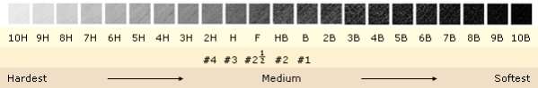
Figure 3: Graphite grading scale
Figure 4: Resistance proportional to length
Figure 5: Resistance proportional to cross sectional area
Experiment 2 (cross sectional area)
Table 1: Experiment 1 (length)
Table 2: Experiment 2 (cross sectional area)
Table 2: Experiment 3 (pencil type)
Research Background
The electrical conductivity of a substance is a measure of the ease with which the valence electrons move throughout its structure, and thus is dictated by its bonding. Metallic bonding produces the greatest conductivity, as it involves a lattice of positively charged nuclei, with electrons free to move throughout the lattice (Science Daily, 2010).


Figure 1: Metallic Bonding
Hence, when an electrical charge is applied to the metal, the electrons are able to easily move through it and therefore it can be said to be a good conductor. Substances bound by covalent bonding, on the other hand, are usually poor conductors (called insulators) as the electrons are tightly held within the covalent bonds. They are materials that do not permit the free flow of electrons.
While a conductor lets the flow electrons pass through and an insulator impede the flow of electrons. A resistor’s resistance limits the flow of electrons throughout the circuit. The resistor’s ability to reduce the current is called resistance and is measured in units of ohms (symbol: Ω). Resistance is caused by the collisions of the electrons with positive ions in the lattice.
Ohm’s Law

The resistor’s current(I)in amps (A) is equal to the resistor’s voltageVin volts (V) divided by the resistanceRin ohms (Ω)
Electrical current (Amps) is the rate at which charged particles move from one part of the conductor to another current has the symbol I. Voltage is a measure of the difference inelectrical energybetween two parts of a circuit. The bigger the difference in energy, the bigger the voltage.
An ohmic resistor obeys the ohm’s law. Ohm’s law states that the proportional energy drop across a resistor is proportional to its resistance and the current the flows through is. This can be represented in the form of a formula:
V=IR
So, if a current of 1 A is passing through a conductor of resistance of 1Ω the potential difference between the ends of the conductor will be 1V. Additionally, resistance is equal to voltage divided by current, and voltage is equal to current multiply by resistance. Therefore, in a circuit, if a resistor’s resistance is equal to voltage divided by current, the resistor is ohmic.
Resistivity is the measure of resistance inherent to a particular material.
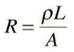
Provided that the dimensions (length and cross sectional area) of any conductor do not change, its resistance will remain the same. If two conductors of exactly the same dimensions have a different resistance, they must be made of different materials. Resistivity is given the symbol (ρ) called rho. The resistivity of a material is defined as the resistance of a piece of material having a length of one metre and a cross sectional area of one square metre.
Graphite is a pure carbon substance, where three of its valence electrons are covalently bonded to three other carbon atoms, forming a layered structure. However, the fourth valence electron is left unbonded, and thus is able to move freely. These valence electrons allow the flow of electricity through the substance in certain directions when an electrical current is applied to graphite.

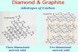
Figure 2: Molecular structure of diamond and graphite
Each carbon atom in graphite is covalently bonded to three neighboring carbon atoms and these form layers of hexagonal network which are separated by a large distance. Although the fourth valence electrons are remained free which enables the electrons to flow through graphite this makes graphite a good conductor of electricity. Although this does not happen in diamond, each of the carbon atoms in diamond makes bonds with four other carbon atoms. So there is no free electron with carbon atoms to conduct electricity blocking the flow of electrons.
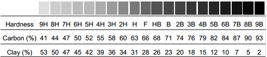
Figure 3: Graphite grading scale
The “lead” in pencil is made up of a combination of graphite and clay, with wax and other additives in small quantities. Clay, unlike graphite, is an insulator as it does not conduct electricity well, due to the covalent bonds holding valence electrons tightly in place. This is because clay is mainly made out of silicate minerals; these minerals have very low conductivity which makes them good insulator. The shade of pencil is dependent on percentage of each component. Pencils range from 9H, with 41% graphite and 53% clay, to 9B, with 93% graphite and 2% clay.
Given that graphite is more conductive than clay, as the concentration of graphite increases, the conductivity should increase. The resistance of an object, a measure of the conductivity of a circuit component, this can be calculated using Ohm’s law explained before above, which considers electrical resistance as the ratio of the voltage applied to the current which flows through it, or the degree to which the voltage is resisted.
Factors that would be affect the resistance of the graphite are length, cross sectional area and temperature. As the length of the conductor is shorter it would allow more electrons to pass through at a higher rate rather than a longer one. While as the radius of the cross sectional area of a conductor (or thickness) is wider the more electrons can pass through compared to a narrower conductor restricting high rate of flow of electrons. Finally, although temperature would not be tested as it would have less effect on the resistance of the conductor. As the temperature of the conductor increase stronger the resistance as the protons inside the conductor would be vibrating slowing the flow of electrons.
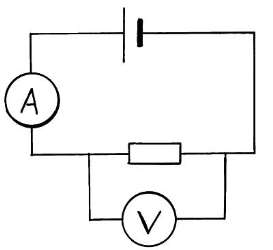
Resistance isproportional to length. If the pencil’s resistor has a different length and give each a particular potential difference across its ends, the longer the pencil’s resistor the less volts each centimetre of it will get. A smaller potential gradient in the graph would have fewer volts per metre means current decreases with increased length and resistance increases.
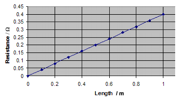
Figure 4: Resistance proportional to length
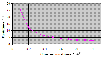
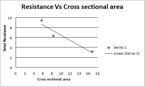
Figure 5: Resistance proportional to cross sectional area
Resistance isinversely proportional to cross sectional area. The bigger the cross sectional area of the pencil’s resistor the greater the number of flow of electrons can pass through the conductor. If the length of the pencil’s resistor does not change the conductor still gets the same number of volts across the potential gradient does not change and so the average drift velocity of individual electrons does not change.
Aim
Experiment 1
The aim of this experiment is to test if the length of a pencil resistor affects the output of the circuit.
Experiment 2
The aim of this experiment is to test if the cross sectional area of a pencil resistor affects the output of the circuit.
Experiment 3
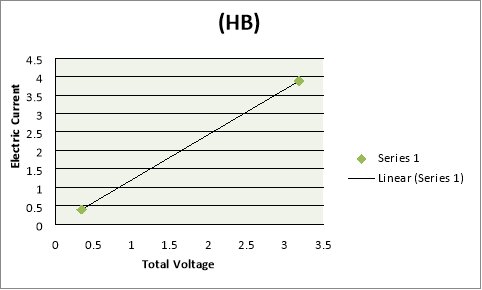
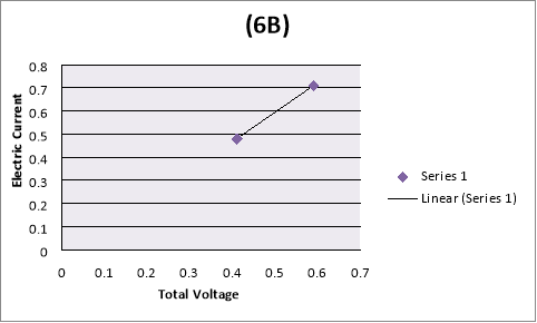
The aim of this experiment is to test if the type of a pencil resistor (HB, 2H, 2B and 6B) affects the output of the circuit.
Hypothesis
Experiment 1
It is predicted that the longer the length of a pencil’s resistor the lower the current as the electrons would have to travel further which gives a higher resistance.
Experiment 2
It is predicted that the thicker the cross sectional area of the pencil’s resistor the more electrons would flow through which gives a low resistance.
Experiment 3
It is predicted that as the concentration of clay in the pencil’s resistor increases, the resistance increases.
Justification of hypothesis
Experiment 1
As the length of a conductor increases, the resistance increases. Increasing the length of the graphite in the pencil will increase the resistance of the whole circuit. As the resistance through the pencil increases, more voltage is used there and the potential energy across the circuit decreases.
Experiment 2
As the cross sectional area of the conductor increases, the resistance decreases. As the radius of the cross sectional area of a conductor (or thickness) is wider, the more electrons can pass through compared to a narrower conductor restricting high rate of flow of electrons.
Experiment 3
Graphite is more conductive than clay, as the concentration of clay in the pencil’s resistor increases, the resistance increases. Clay compared to graphite is an insulator and does not conduct with electricity well blocking the flow of electrons. This shows that a 2B would be more conductive than a HB as it contains more graphite than clay.
Materials |
|
|
Pencils (HB,2H,2B,6B) |
x3(HB),x3(2H),x3(2B),x3(6B) |
|
Insulated alligator clip set |
X6 |
|
Power supply |
X1 |
|
Multimeter (Amp meter and Volt meter) |
X2 |
|
Ruler (30cm) |
X1 |
Method
Experiment 1 (length)
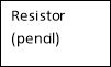
The circuit was setup using two alligator clips, in a power battery. Then one wire was attached to one end of the terminal of the battery and the other end of the wire was attached on to one end of the pencil’s graphite. Next, the seconds wire was attached to the other end of the terminal of the battery and the other end of the wire was attached into one end of the pencil’s graphite. Finally, the two multimeter was placed next to the pencil and the two wires from the multimeters were attached on to the ends of the pencil. The circuit was tested with different lengths of pencils. Then the experiment was recorded in a table and graph.
Experiment 2 (cross sectional area)
The circuit was setup using two alligator clips, in a power battery. Then one wire was attached to one end of the terminal of the battery and the other end of the wire was attached on to one end of the pencil’s graphite. Next, the seconds wire was attached to the other end of the terminal of the battery and the other end of the wire was attached into one end of the pencil’s graphite. Finally, the two multimeter was placed next to the pencil and the two wires from the multimeters were attached on to the ends of the pencil. The circuit was tested with different cross sectional area of pencils. Then the experiment was recorded in a table and graph.
Experiment 3 (type of pencil)
The circuit was setup using two alligator clips, in a power battery. Then one wire was attached to one end of the terminal of the battery and the other end of the wire was attached on to one end of the pencil’s graphite. Next, the seconds wire was attached to the other end of the terminal of the battery and the other end of the wire was attached into one end of the pencil’s graphite. Finally, the two multimeter was placed next to the pencil and the two wires from the multimeters were attached on to the ends of the pencil. The circuit was tested comparing HB, 2H, 2B and 6B. Then the experiment was recorded in a table and graph.
Diagram of the experiment


Ohm’s Law

The resistance was then measured by dividing the total voltage (V) and the current (I).
Example:
Pencil 1 (HB 8.5 cm)


Variables
Independent Variables
The resistor (pencil)
Dependent Variables
The volt and the amp meter
Controlled Variables
The voltage
Results
Table 1: Experiment 1 (length)
|
Length |
||||
|
Voltage of battery |
total voltage (V) |
Current (A) |
Resistance (Ω) |
|
|
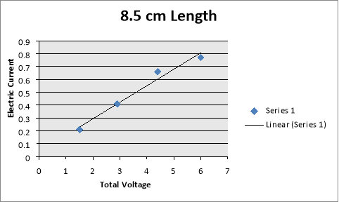
Pencil 1 (HB 8.5cm) |
2 V |
1.5 V |
0.21 A |
7.14 Ω |
|
4 V |
2.9 V |
0.41 A |
7.07 Ω |
|
|
6 V |
4.4 V |
0.66 A |
6.67 Ω |
|
|
8 V |
6 V |
0.77 A |
7.79 Ω |
|
|
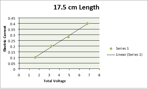
Pencil 2 (HB 17.5cm) |
2 V |
1.6 V |
0.1 A |
16 Ω |
|
4 V |
3.2 V |
0.2 A |
16 Ω |
|
|
6 V |
4.9 V |
0.28 A |
17.5 Ω |
|
|
8 V |
6.8 V |
0.4 A |
17 Ω |
|
|
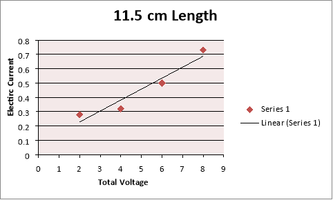
Pencil 3 (HB 11.5cm) |
2 V |
2 V |
0.18 A |
11.11 Ω |
|
4 V |
4 V |
0.32 A |
12.5 Ω |
|
|
6 V |
6 V |
0.5 A |
12 Ω |
|
|
8 V |
8 V |
0.73 A |
10.96 Ω |
|
|
Pencil 4 (HB 7cm) |
2 V |
1.9 V |
0.27 A |
7.03 Ω |
|
4 V |
3.9 V |
0.56 A |
6.96 Ω |
|
|
6 V |
5 V |
0.79 A |
6.33 Ω |
|
|
8 V |
6.7 V |
1.2 A |
5.58 Ω |
|
Total Resistance
Pencil 1
7.14 Ω + 7.07 Ω + 6.67 Ω+ 7.79 Ω/ 4= 7.1675 Ω
Pencil 2
16 Ω+ 16 Ω+ 17.5 Ω+ 17 Ω/4= 16.625 Ω
Pencil 3
11.11 Ω+ 12.5 Ω+ 12 Ω+ 10.96 Ω/ 4= 11.6425 Ω
Pencil 4
7.03 Ω+ 6.96 Ω+ 6.33 Ω+ 5.58 Ω/4= 6.475 Ω
Pencil 1
Pencil 2
Pencil 3
Pencil 4
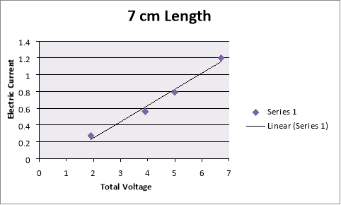
Table 2: Experiment 2 (cross sectional area)
|
Cross sectional area |
||||
|
Voltage of battery |
total voltage (V) |
Current (A) |
Resistance (Ω) |
|
|
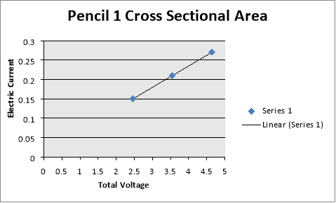
Pencil 1 (HB 17.5cm) |
4 V |
1.07 V |
0.15 A |
16.40 Ω |
|
6 V |
1.53 V |
0.21 A |
16.90 Ω |
|
|
8 V |
1.99 V |
0.27 A |
17.19 Ω |
|
|
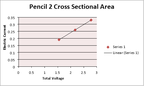
Pencil 2 (HB 17.5cm) |
4 V |
1.55 V |
0.19 A |
8.16 Ω |
|
6 V |
2.17 V |
0.26 A |
8.35 Ω |
|
|
8 V |
2.78 V |
0.33 A |
8.42 Ω |
|
|
Pencil 3 (HB 17.5cm) |
4 V |
2.46 V |
0.18 A |
5.94 Ω |
|
6 V |
3.55 V |
0.27 A |
5.67 Ω |
|
|
8 V |
4.64 V |
0.36 A |
5.53 Ω |
|
Cross Sectional Area
A=2πr2
Pencil 1
3.14 x 1 =3.14
Pencil 2
3.14 x 2= 6.28
Pencil 3
3.14 x 3= 9.42
Total resistance
Pencil 1
16.40 Ω+ 16.90 Ω+ 17.19 Ω/ 3= 16.83 Ω
Pencil 2
8.16 Ω+ 8.35 Ω+ 8.42 Ω/ 3= 8.31 Ω
Pencil 3
5.94 Ω+ 5.67 Ω+ 5.53 Ω/3= 5.71 Ω
Pencil 1
Pencil 2
Pencil 3
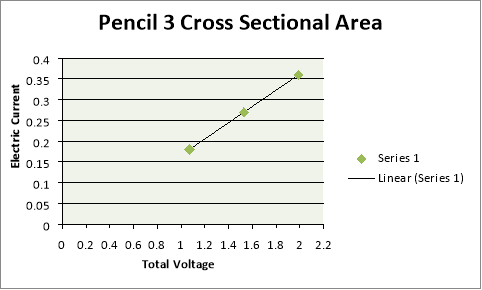
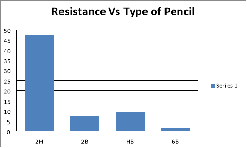
Table 2: Experiment 3 (pencil type)
|
Pencil types |
||||
|
Voltage of battery |
total voltage (V) |
Current (A) |
Resistance (Ω) |
|
|
Pencil 1 (2H 10.5cm) |
6V |
7.35 V |
0.16 A |
45.94 Ω |
|
8V |
9.70 V |
0.20 A |
48.50 Ω |
|
|
Pencil 2 (2B 10.5cm) |
6V |
2.63 V |
0.35 A |
7.51 Ω |
|
8V |
3.18 V |
0.42 A |
7.57 Ω |
|
|
Pencil 3 (HB 10.5cm) |
6 V |
3.18 V |
0.34 A |
9.35 Ω |
|
8V |
3.88 V |
0.40 A |
9.7 Ω |
|
|
Pencil 4 (6B 10.5cm) |
6V |
0.59 V |
0.41 A |
1.44 Ω |
|
8V |
0.71 V |
0.48 A |
1.48 Ω |
|
Total Resistance
Pencil 1
48.50 Ω+ 45.94 Ω/ 2= 47.22 Ω
Pencil 2
7.57 Ω+ 7.51 Ω/ 2= 7.54 Ω
Pencil 3
9.35 Ω+ 9.7 Ω/ 2= 9.525 Ω
Pencil 4
1.44 Ω+ 1.48 Ω/ 2= 1.46 Ω
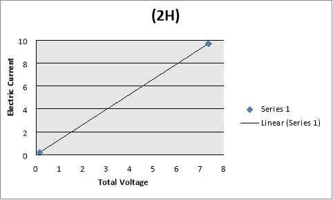
Pencil 1 (2H)
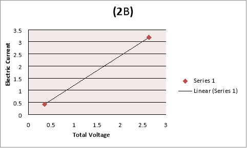
Pencil 2 (2B)
Pencil 3 (HB)
Pencil 4 (6B)
Discussion
Experiment 1 According to the data and the graph shown previously it supports the hypothesis for all the experiments. For experiment 1, it supports the hypothesis that as the length increase the resistance increase. Using the ohm’s law formula:
For Pencil 2 (HB 17.5cm) with an applied volts of 2V, it shows that the total voltage was decrease to 1.6V with a current of 0.1 A and resistance of 16Ω. Compared to Pencil 4 (HB 7cm) with an applied volt of 2V, it shows that the total voltage was decreasing to 1.9V a 0.1 difference in voltage. With a current of 0.27A and a resistance of 7.03Ω it shows that as the length of the pencil resistor increases the resistance increase. Increasing the length of the graphite in the pencil will increase the resistance of the whole circuit as the flow of electrons would have to travel longer than a short pencil resistor.
Experiment 2
For experiment 2, referring to the graphs and tables it supports the hypothesis that as the cross section area of the conductor increases, the resistance decrease. For Pencil 1 with an applied of 4V, it shows that the total voltage was decrease to 2.46V with a current of 0.15A and resistance of 16.40 Ω. Compared to Pencil 3 with an applied volt of 4V, it shows that the total voltage was decreasing to 1.55V a 2.58 difference in voltage. With a current of 0.19A and a resistance of 7.03 Ω it shows that as the cross section area of the pencil resistor increases, the resistance decreases. As the radius of the cross sectional area of a conductor (or thickness) is wider, the more electrons can pass through compared to a narrower conductor restricting high rate of flow of electrons.
Experiment 3
For the experiment 3, it supports the hypothesis that as the concentration of clay in the pencil’s resistor increases, the resistance increases. For Pencil 1 (2H 10.5cm) with an applied volt of 6V, it shows that the total voltage was decrease to
Graphite is more conductive than clay, as the concentration of clay in the pencil’s resistor increases, the resistance increases. Clay compared to graphite is an insulator and does not conduct with electricity well blocking the flow of electrons. This shows that a 2B would be more conductive than a HB as it contains more graphite than clay.
Cite This Work
To export a reference to this article please select a referencing stye below:
Related Services
View all


DMCA / Removal Request
If you are the original writer of this essay and no longer wish to have your work published on UKEssays.com then please click the following link to email our support team:
Request essay removal